F6300 Power System Simulator User Guide
72A-2337-01 Rev. B 11/05 5-9
Removing and Replacing Circuit Boards
Doble Customer Service may recommend that a circuit board be replaced to remedy an
operating problem. None of the solid-state circuit boards requires user calibration or adjustment.
Table 5.3 contains a list of slot numbers and circuit boards in the F6300
.
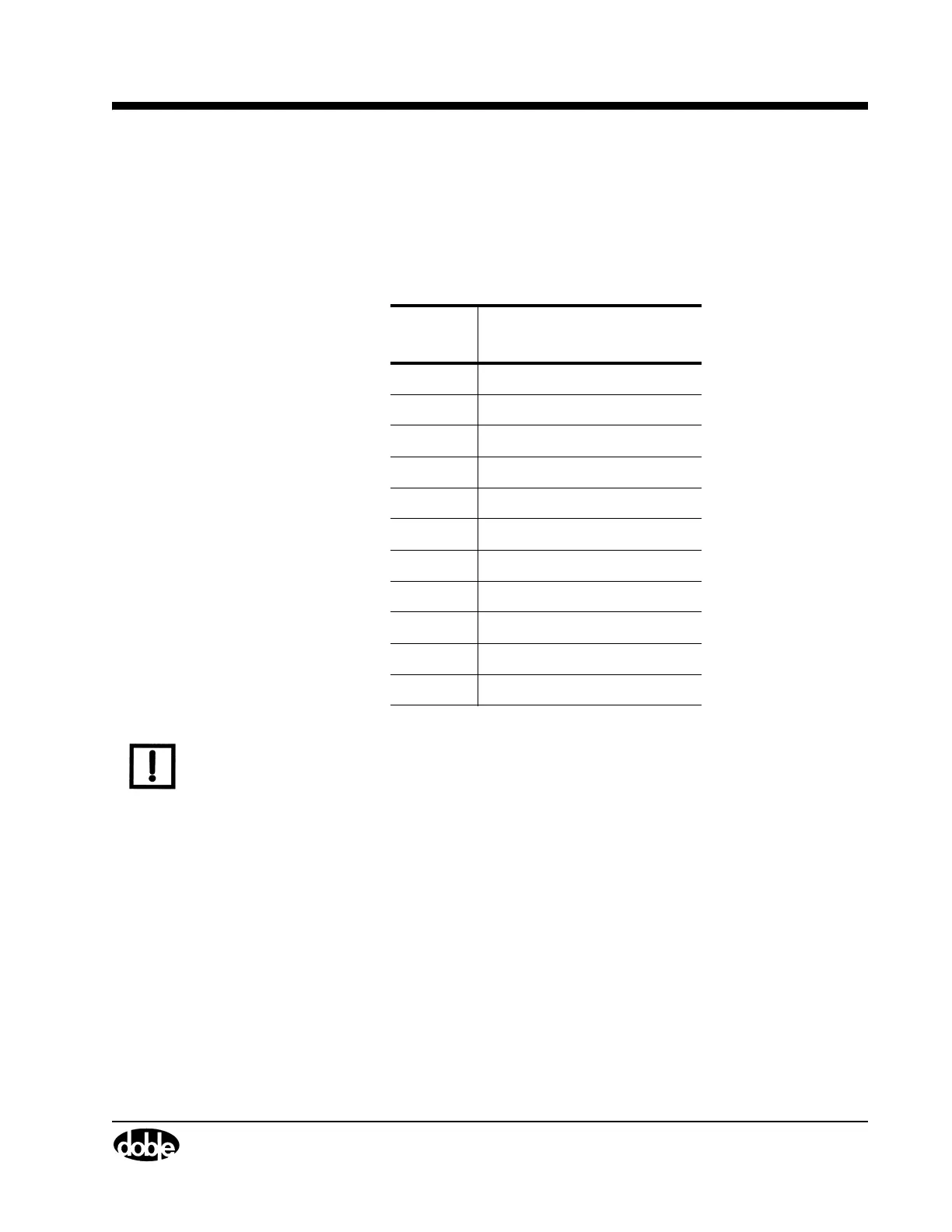
Table 5.3 Circuit Board Slot Numbers
Slot
Number
Circuit Board
Slot 1 Spare slot (Front)
Slot 2 Spare slot
Slot 3 CPU board
Slot 4 Analog Multiplexer board
Slot 5 Current amplifier #1
Slot 6 Current amplifier #2
Slot 7 Current amplifier #3
Slot 8 Current amplifier #4
Slot 9 Current amplifier #5
Slot 10 Current amplifier #6
Slot 11 Power supply (Back)
NOTE Remove or insert printed circuit assemblies carefully to avoid damage to their mating
connectors. To ensure that new boards go into their correct locations, replace them
individually.
Contact Doble for a replacement circuit board, or obtain one from your company inventory of
replacement parts, if available.
To replace a circuit board:
1. Turn the instrument off.
2. Remove the power cord.
3. Disconnect all external cables from the instrument.
4. Remove the instrument cover.
5. Remove the capture rail.
6. Disconnect any circuit board ribbon cables required to perform the replacement.
7. Unscrew the captive fasteners on the circuit board.
8. Firmly grasp the defective board and pull it straight up.
9. Place the new board firmly in the slot and make sure it is squarely seated.
10. Re-attach ribbon cables if necessary.