CT100 inverter Detailed instructions of function parameters
110
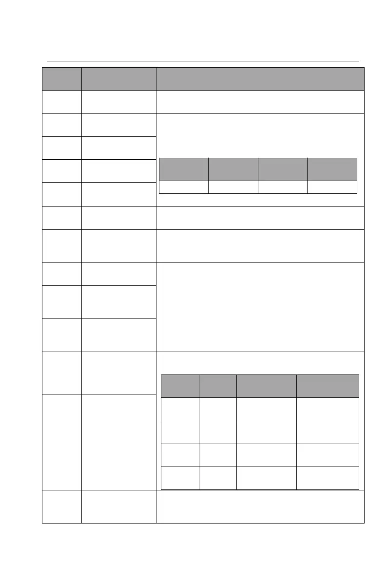
Shield the function of multi-speed terminals and
keep the set value as the current status.
Multi-step speed
terminal 1
16 steps speed control can be realized by the
combination of these four terminals.
Note: Multi-step speed 1 is the low bit and multi-step
speed 4 is high bit.
Multi-step speed
terminal 2
Multi-step speed
terminal 3
Multi-step speed
terminal 4
Restart simple PLC and clear the memory state of
PLC.
Program pause during PLC implement. Run at the
current speed step. After cancel the function, simple
PLC continues to run.
X setting and Y
setting switching
The function can realize the switching between the
frequency setting channels.
(X+Y) setting and
X setting
switching
(X+Y) setting and
Y setting
switching
Select four groups of ACC/DEC time by the
combination of the two terminals:
Ensure that the inverter is not affected by external
signals (except for the stop command) and maintain
the current output frequency.