80
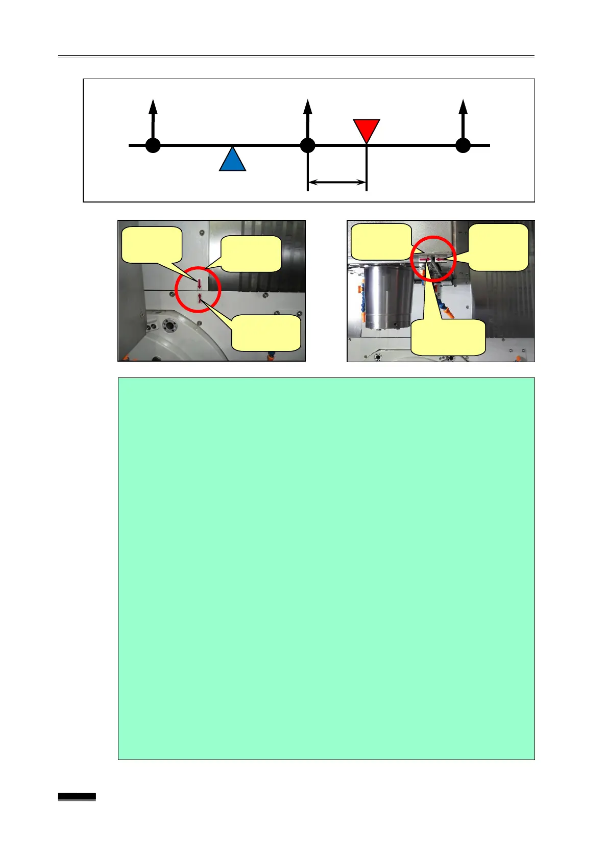
7. Adjustment of reference points of respective axes and manual TCP adjustment
reference
reference
reference
reference
fixing
reference
reference
Note) Forced reference point setting of the X-axis and Y-axis
(1) By moving the X- and Y-axis using the test indicator, accurately match the
table center to the spindle center. (Refer to “X-axis and Y-axis reference
point resetting” above.)
(2) Change the Parameter No.1815 “A” and “Y” field b4(APZ) from “1” to
“0 ”.
☞ Where the “PW0000 POWER MUST BE OFF” and the “P/S Alarm 300
nAxis Need ZRN” alarms are activated.
(3) Once again, change the Parameter No.1815 “X” and “Y” field b4(APZ)
from “0” to “1”, and turn off the emergency stop NC Power.
(4) In the case of NC Power On Machine Ready, the machine’s position
on the CRT screen is changed to the first origin point dimension (X0.000,
Y0.000) described in Parameter No. 1240 “X” and “Y ” term and the
resetting of the corresponding axis is completed.
※ If the forced reference point setting is set once, the position is
memorized regardless of Power “On/Off”. In the case of Servo Drive
Battery Alarm or if Parameter No. 1815 b4(APZ) becomes “0” (which
means that the reference point setting of the corresponding axis has
been lost), it is necessary to reset the reference point.
Grid Shift (Parameter No. 1850)