81
7. Adjustment of reference points of respective axes and manual TCP adjustment
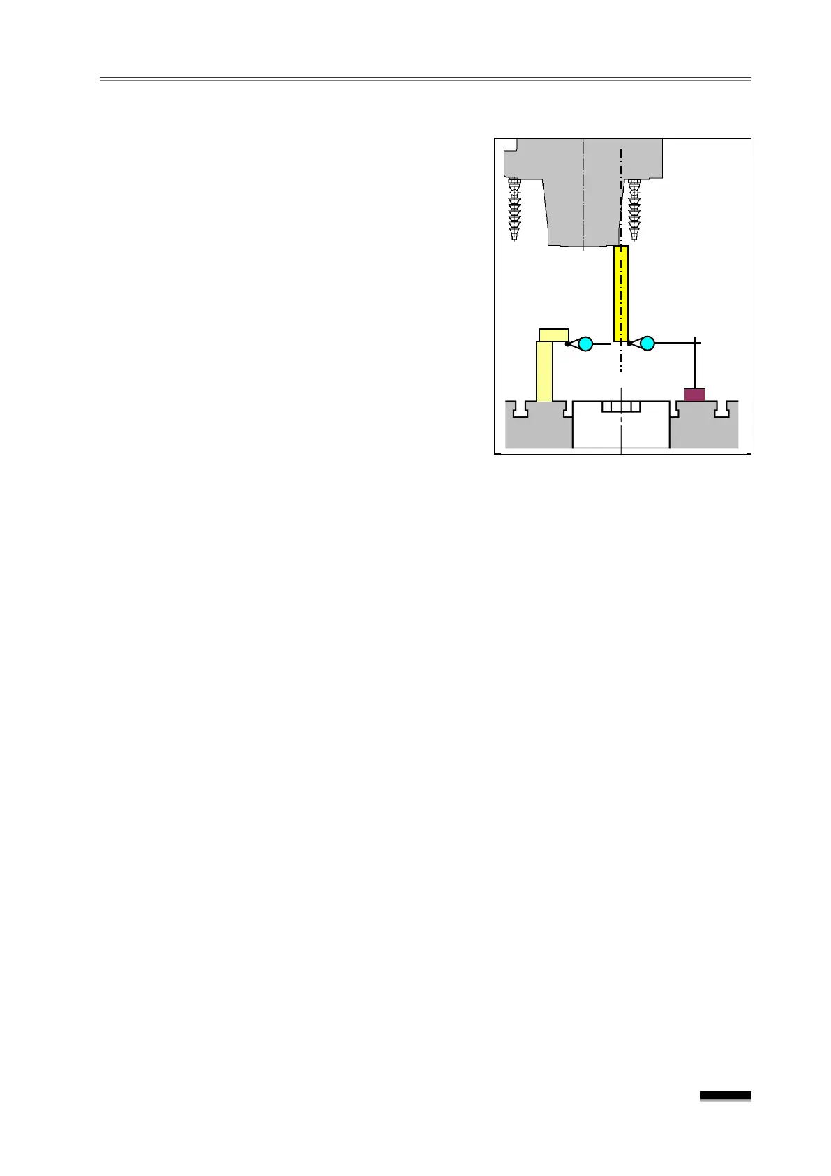
7.2 Z-axis reference point resetting (Z-axis Stroke: 400mm)
-bar into the spindle, set up a block
gage (around 100mm) so that the
measurement can be made from the bottom,
and set the indicator to
“0.”
-axis in the Handle Mode, so that
the end of the Test-Bar touches the indicator to
set it to "0".
3) Calculate the distance from Z0 position by the
following equation.
Test Bar Length
Block Gage Height - 150
▪ For the DVF 5000, when the distance from
the table top to the Spindle Gage Line is
"150mm,” “Z-400.000”
Ex) If the Block Gauge : 100mm, Test bar : 310mm, then : 310 + 100
150 = 260
In other words, in this case, the position reached when -260.000 has been
transferred in the Z-axis machine coordinate is -400.000, which is the end of the Z-
axis stroke “- ”
direction. And, for the machine reference point position, the position
reached when 140.00 has been transferred in the + direction is the Z-axis
reference point.
’s position on the CRT screen and enter the error amount into the
Parameter No.1850 Z-axis field.
▪ If the Parameter already has a certain number, “+Input” the error amount.
☞ In this case, if the Parameter #1815 “X” or “B” field b4(APZ) changes from “1”
“0”, the “PW0000 POWER MUST BE OFF” and “P/S Alarm 300 nAxis Need ZRN
alarms will be activated on the screen.
the Z-axis with the “JOG” or
HANDLE
feed in the direction of reference point
return to a position near the front of the reference point mark (within 1Grid : within
10mm).
▪ Rapidly move the axis by several Grids or more.
While pressing the
JOG+
switch of the Z-axis in the
R E F. RTN
Mode, perform
reference point return in the “+ ” direction. (Keep pressing the
JOG+
reference point return is complete and the axis stops.)
☞ b4(APZ) of the “Z ” field of the parameter #1815 changes from 0” to “1”
alarm is cleared.
the Z-axis to the Z-260 position, measure as above, and if the
measurement is within +0.005mm, complete the reference point return.