79
7. Adjustment of reference points of respective axes and manual TCP adjustment
7. Adjustment of reference points of respective axes and manual TCP adjustment
7.1 X- and Y-axis reference point resetting
the X-axis or Y-axis reference point with the Grid Shift adjustment.
The reference point mark is attached near the X- or Y-axis reference point with which the
reference point can be set manually.
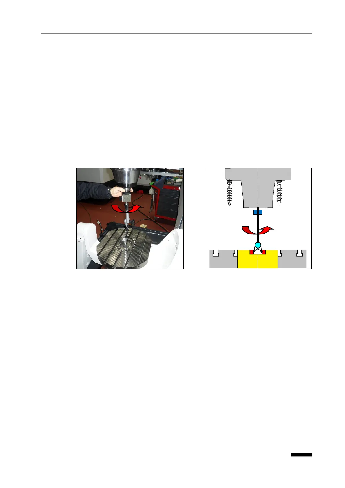
the X- and Y-axis to the middle of the stroke (X0., Y0.) and install an indicator
on the spindle.
the eccentricity of the spindle and the table center bush in the X- and Y-axis
directions by rotating the spindle while the indicator needle makes contact with the inner
diameter of the center bush at the center of the table, and adjust the eccentricity to the
accurate value by moving the axis with the handle.
Check the machine’s position on the CRT screen, and enter the error amount into the
Parameter No.1850
“X ” or “Y” field by comparing it with X0.000 or Y0.000.
▪ If the Parameter already has a certain number, “+Input” the error amount.
☞ In this case, if the Parameter #1815 “X” or “B” field b4(APZ) changes from “1”
“0 ”, the “PW0000 POWER MUST BE OFF” and the “
ZRN” Alarms will be activated on the screen.
the X-axis or Y-axis 50mm or more in the “-” direction with the “JOG” or
“HANDLE”
feed, and then transfer in the opposite direction to the position near the
of the reference point mark (within 1Grid : within 10mm).
the “JOG+” switch of the X or Y-axis in the “R EF. R TN ” Mode, perform
reference point return in the “+ ” direction. (Keep pressing the “JOG+”
reference point return is complete and the axis stops.)
☞ b4(APZ) of the “X” or “Y” field of Parameter #1815 changes from 0” to “1”
alarm is cleared.
the X- or Y-axis reference point again, and if it is within ±0.005mm,
X or Y-axis reference point setting has been completed.