57
6. Machine Accuracy Measurement and Adjustment
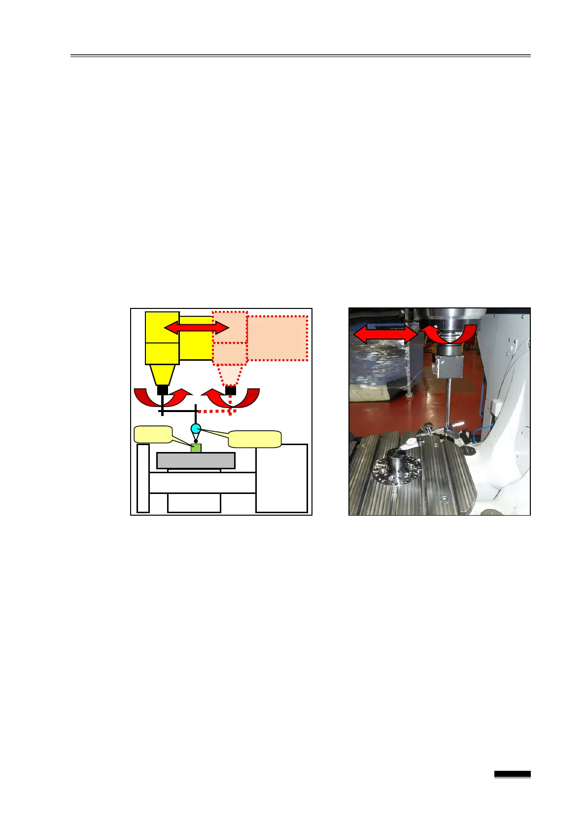
6.8 Spindle centerline and Y-axis movement squareness (Y-Z plane)
① Install the indicator hold on the end of the spindle and bend so that the needle is
about 150mm from the spindle center and place the axis near X0., Y150.
② Rotate the spindle by hand until the indicator is parallel to the Y-axis inside the table,
and then place the block on the table top to perform “0” setting.
③ Rotate the spindle backwards by hand, and measure the block with the indicator in
the same position by moving the Y-axis.
▶
Measurement position : When the spindle is in the Y150. and Y-150. positions
height of the block at a certain point on the table surface.
▶ Tolerance : 0.015mm / 300mm
In general, it is highly unlikely that deformations of the axial or spindle squareness will
occur in an L/M guide machine. However, in the case of squareness deformation due to
a severe collision, etc., the squareness can be corrected by adjusting the thickness of
the liner to be assembled in the spindle housing assembly area.
※ In this case, the squareness must be corrected after loosening the spindle housing
fixing bolt to see if it has been pushed to one side due to an unexpected impact; and
since this accuracy is related to “6.13 Spindle centerline and Z-axis feed parallelism,
take the measurement first, and then review the error amount and direction before