- 202 -
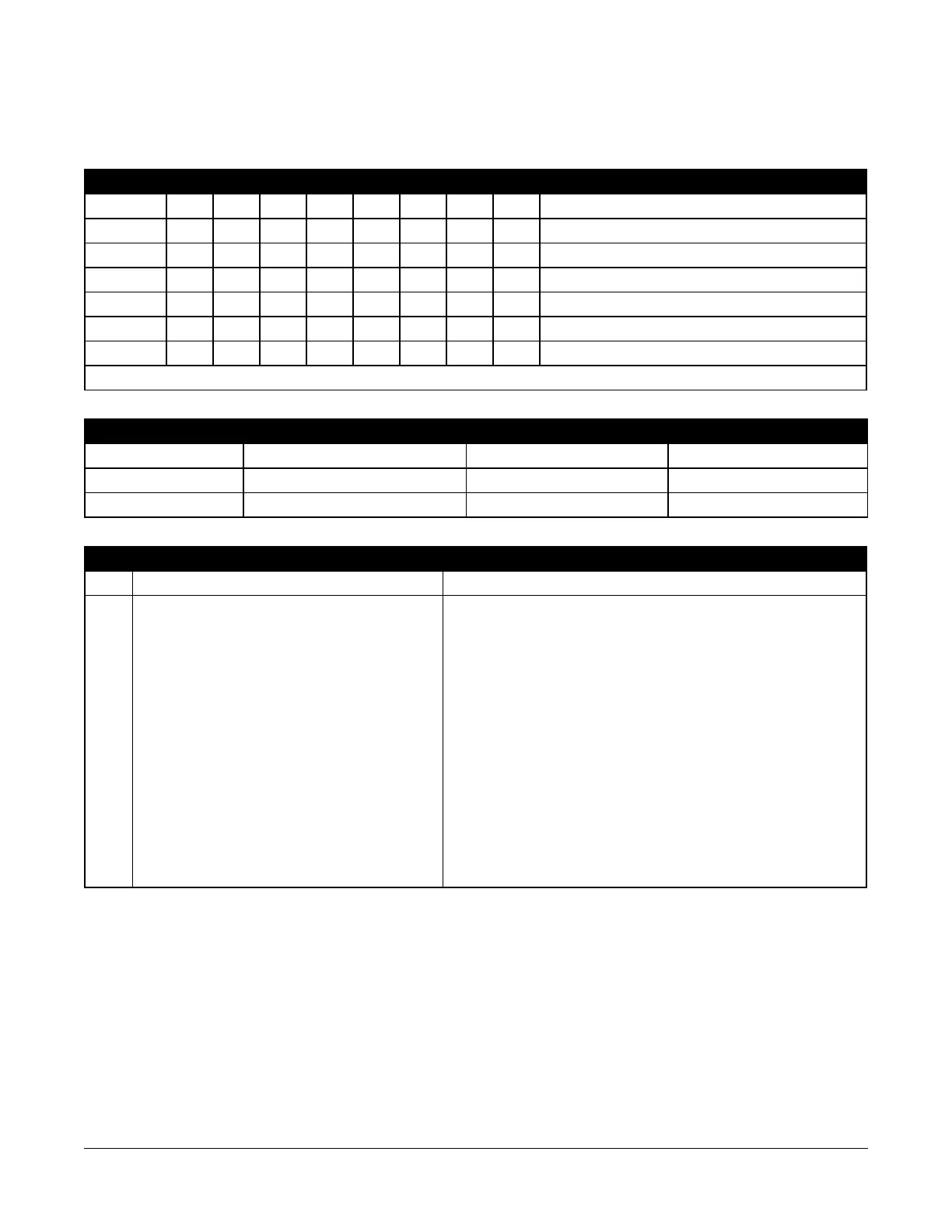
Appendix 3: Template Programming Tables
The following tables show the programming options for template programming digits 1-5.
Digit 1 – Zones 1-8 Definition Options
Note: A “0” in the digit 1 location indicates that the default settings for the first 8 zones
Option Zn1 Zn2 Zn3 Zn4 Zn5 Zn6 Zn7 Zn8 Zone Definitions (Options 1- 6)
1 001 003 003 003 004 004 004 004 001 Delay 1
2 001 003 003 005 005 005 005 008 003 Instant
3 001 003 003 005 005 005 005 007 004 Interior
4 001 001 003 003 003 003 003 003 005 Interior Stay/Away
5 001 003 003 006 005 005 005 005 006 Delayed Stay/Away
6 001 003 003 006 005 005 005 008 007 Delayed 24Hr. Fire
7 (ADT)
001 001 006 006 006 001 001 001 008 Standard 24Hr. Fire (Wireless)
Refer to "[001] Zone Types" on page 64 for details.
Digit 2 – System EOL Configuration Options
Option [13] bit 1 [13] bit 2
1 NC Loops ON OFF
2 SEOL OFF OFF
3 DEOL OFF ON
Digit 3 – Reporting Code Communication Options
Entry Template Programming
1 Disabled [380] Comm Toggles 1 - Bit 1 Communications Enabled - Off
2 Receiver 1 and 2 SIA with Backup [380] Comm Toggles 1 - Bit 1 Communications Enabled - On
[350] Communicator Formats - [001] Receiver 1 - 04 SIA
[350] Communicator Formats - [002] Receiver 2 - 04 SIA
[350] Communicator Formats - [003] Receiver 3 - 04 SIA
[350] Communicator Formats - [004] Receiver 4 - 04 SIA
[381] Comm Toggles 2 - Bit 2 Bell Ringback - Off
[384] Comm Backup - Bit 2 Receiver 2 Backup - On
[384] Comm Backup - Bit 2 Receiver 2 Backup - Off
[384] Comm Backup - Bit 2 Receiver 2 Backup - Off
[300] Comm Path - [001] Receiver 1 - 01 PSTN
[300] Comm Path - [002] Receiver 2 - 01 PSTN
[300] Comm Path - [003] Receiver 3 - 01 PSTN
[300] Comm Path - [004] Receiver 4 - 01 PSTN