Needle bar
Service Instructions 755 A/756 A - 00.0 - 02/2019 51
22. Turn the handwheel further until the screw (14) can be accessed
through the arm shaft crank.
23. Tighten the screw (14).
Setting the needle bar linkage relative to the needle bars
Important
Switching the needle bars on and off safely requires that the needle bar
linkage be set in the exact position relative to the needle bars.
Proper setting
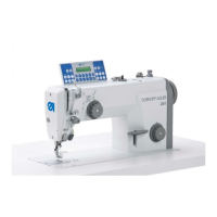
Fig. 46: Assembling the needle bar linkage (6)
The distance between needle bar linkage and clamping ring is 0.25 mm
with the needles switched on and positioned at top dead center.
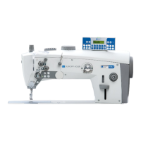
Fig. 47: Assembling the needle bar linkage (7)
To set the needle bar linkage relative to the needles:
24. Lock the machine in place ( p. 15).
The needles are at the top dead center.
25. Remove the handwheel.
26. Remove the handwheel cover.
(16) - Screw (17) - Screw
 Loading...