UPR700 Microprocessor-Based Pressure/Process Indicator 21
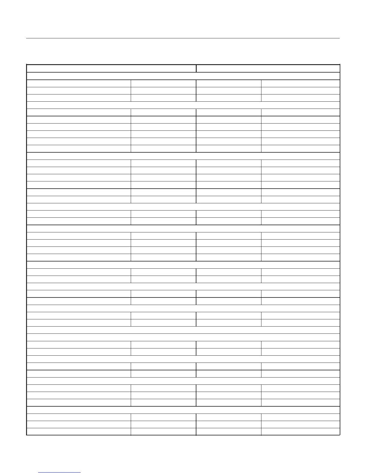
6.2 µPR690 TO UPR700 WIRING CONVERSION TABLE
UPR700 Terminal µPR690 Terminal
Power
120 / 240 VAC 53 31
Line Neutral 54 32
Protective Ground 55 33
Transducer Dynisco Cable Color
Signal + Linear (+) 12 6 Red
Signal - Linear (-) 13 7 Black
Excitation (+) 16 8 White
Excitation (-) 17 9 Green
CAL 1 17 10 Blue
CAL 2 14 11 Orange
Alarms
A1 (N.O.) 45 24
A1 Common 46 25
A1 (N.C.) 47 26
A2 (N.O.) 48 27
A2 Common 49 28
A2 (N.C.) 50 29
Optional Alarm 3
A3 (N.O. / N.C.) 52 21
A3 Common 51 22
Analog Output
Voltage Out + 21 2
Voltage Out - 22 3
Current Out + 21 4
Current Out - 22 5
Optional 2nd Analog
mA/V Out (+) 56 N/A
MA/V Out (-) 57 N/A
OptIonal 24 VDC Transmitter Power Supply
24 VDC (+) 58 N/A
24 VDC (-) 59 N/A
External Reset Contacts
Reset 23 1
Reset Common 24 23
Optional Second Analog Input
Thermocouple Input
TC (+) 1 N/A
TC (-) 3 N/A
mA/V Input
lnput (+) 4 N/A
lnput (-) 3 N/A
RTD Input 3-wire
Red 1 N/A
Black 3 N/A
Black 4 N/A
Serial Communications (RS485 only)
A6016
B6117
COM 62 18