28
In Industrial applications, amplified units have a middle or end number of 4, 5, or 6. The S840-000-
1C has a 4-20 mA signal output; the PT150-7.5M has a 0-5 Vdc signal output, while PT276-5M has
a 0-10 Vdc signal output.
If you have an amplified transducer, or other amplified input, skip to Section 8.4.2.
The UPR700’s default setting is strain gage input. To verify that the input is set for strain gage, press
the FUNC key until
nonE
and
GROUP
show on the display. Press the ▲ key until
5
shows in the
upper display. Press the FUNC key and the upper display should show
Str
while the lower display
shows
PI.TYP
. If not, press the ▼ or ▲ key until the upper display changes to
Str
(for strain gage).
Press the FUNC key to set the value. The upper display changes to
tc
with
SI.TYP
on the lower
display. Press the RESET key to return to the active display.
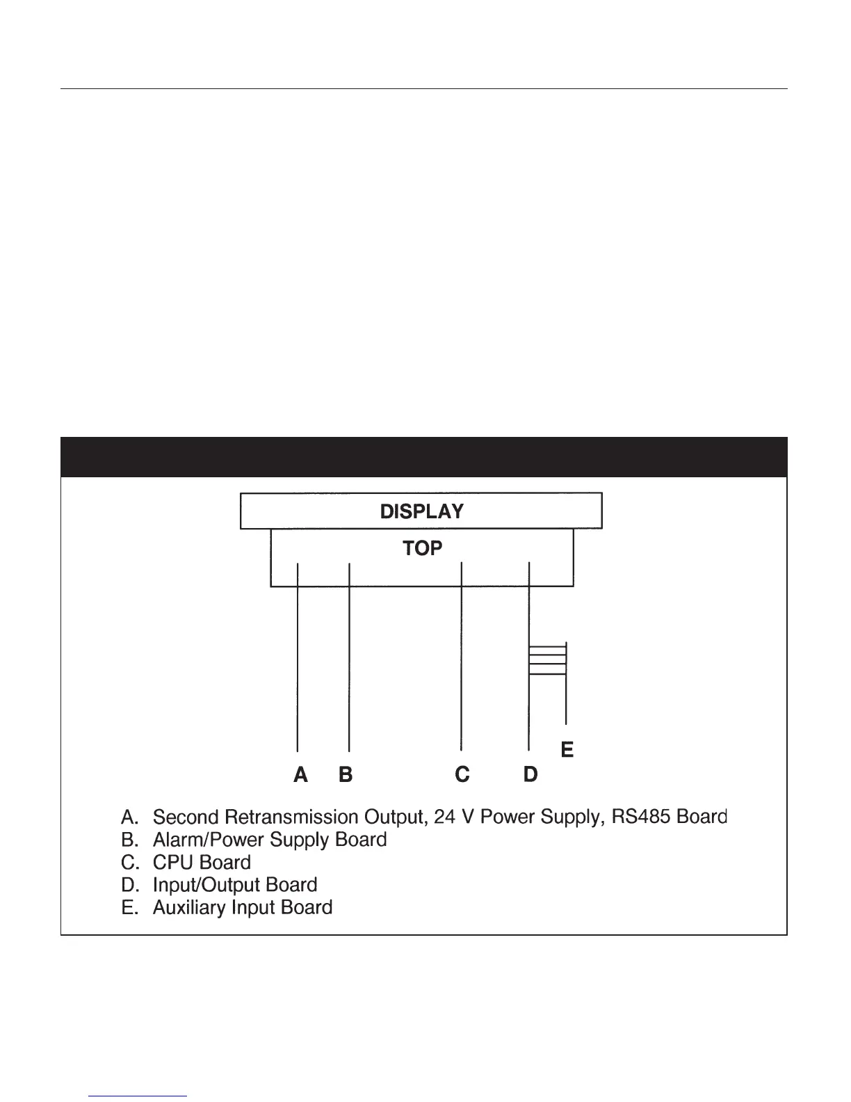
Remember to change the jumper settings to correspond to the proper input as shown in Figure 6 for
board location and Figure 7 for amplified input jumpers.
Fig. 6 UPR700 Board Location