UPR700 Microprocessor-Based Pressure/Process Indicator 27
the lower display changes to
DSP.FL
. Using the ▼ or ▲ keys, select the amount of filtering desired,
from none
(OFF)
to five seconds. When finished, press the FUNC key to lock in the value and
advance to the next parameter.
NOTE: The parameter group legends of instruments manufactured prior to January 1998 refer to the
primary input as “Pressure”, and the secondary input as “Temperature” regardless of the
actual process variable being indicated. When asked in the menu to “Link” an alarm to an
input. “Pressure” is always the main input (upper display), and “Temperature” is always the
secondary input (lower display).
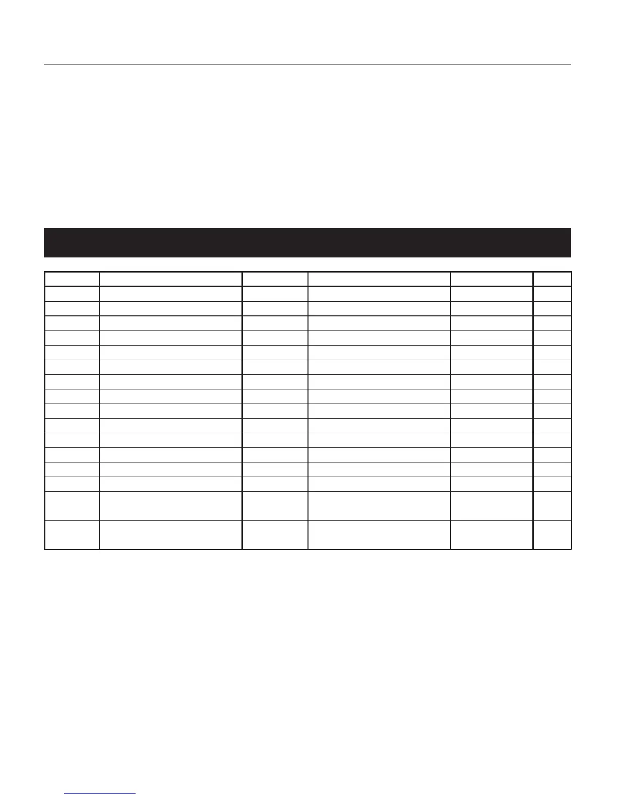
Fig. 5 Parameter Table
Group # Function Mnemonic Choices Default Value
Group 5 Primary Input Selection PI.TYP Str, 0-20, 4-20, 0-5, 0-10 Str
Group 5 Secondary Input Selection SI.TYP OFF, tc, rtd, 0-20, 4-20, 0-10 Tc
Group 4 Shunt Calibration SHUNT OFF,On On
Group 4 Shunt Value SHNT% 40.0 TO 100.0% 80.0%
Group 3 Input Full Scale Value PI.FSV 10 TO 99.950 10000
Group 3 Input Low Scale Value PI.LSV ± 25% OF SFV OF FS V 0
Group 3 Input Decimal Point Position PI.DP None, 1,2,3,4 places None
Group 3 Secondary Input T/C Type Sl.TC tc J, tc CA, tc L, tc n tc J
Group 3 Alarm I Input Channel Link AI.LNK OFF, Prl.ln, Sec.ln Prl.ln
Group 3 Alarm I Type AI.TYP HI, LO, lnhib HI
Group 3 Alarm 2 Input Channel Link A2.LNK OFF, Prl.ln, Sec.ln PrLIn
Group 3 Alarm 2 Type ALTYP HI, 10, lnhib HI
Group 2 Zero Calibration ZERO.C OFF, On, CLEAr OFF
Group 2 Span Calibration SPAN.C OFF, On, CLEAr OFF
Group 1 Alarm I Threshold AL1 TO 110%of span 40% of range
of related input
Group 1 Alarm 2 Threshold AL2 TO 110% of span 60% of range
of related input
In this example, these are functions necessary to allow operation of a pressure/temperature indicator
with two high alarms.
8.4 PRIMARY INPUT SETUP
8.4.1 SETTING THE PRIMARY INPUT TYPE FOR A STRAIN GAGE TRANSDUCER
If using a
Dynisco
transducer, the model number of the transducer will designate its own electrical
output. For example, in plastic melt applications, the PT462E-5M-6/18 or TPT432A-10M-6/18 have
a strain gage (0-3.33 mV/V dc full scale) signal output. Amplified units have a number where the
strain gage units have a letter (E or A). The PT4624-5M-6/18 has a 4-20 mA signal output; the
PT4625-5M-6/18 has a 0-5 Vdc signal output, while PT4626-5M-6/18 has a 0-10 Vdc signal output.