UPR700 Microprocessor-Based Pressure/Process Indicator 45
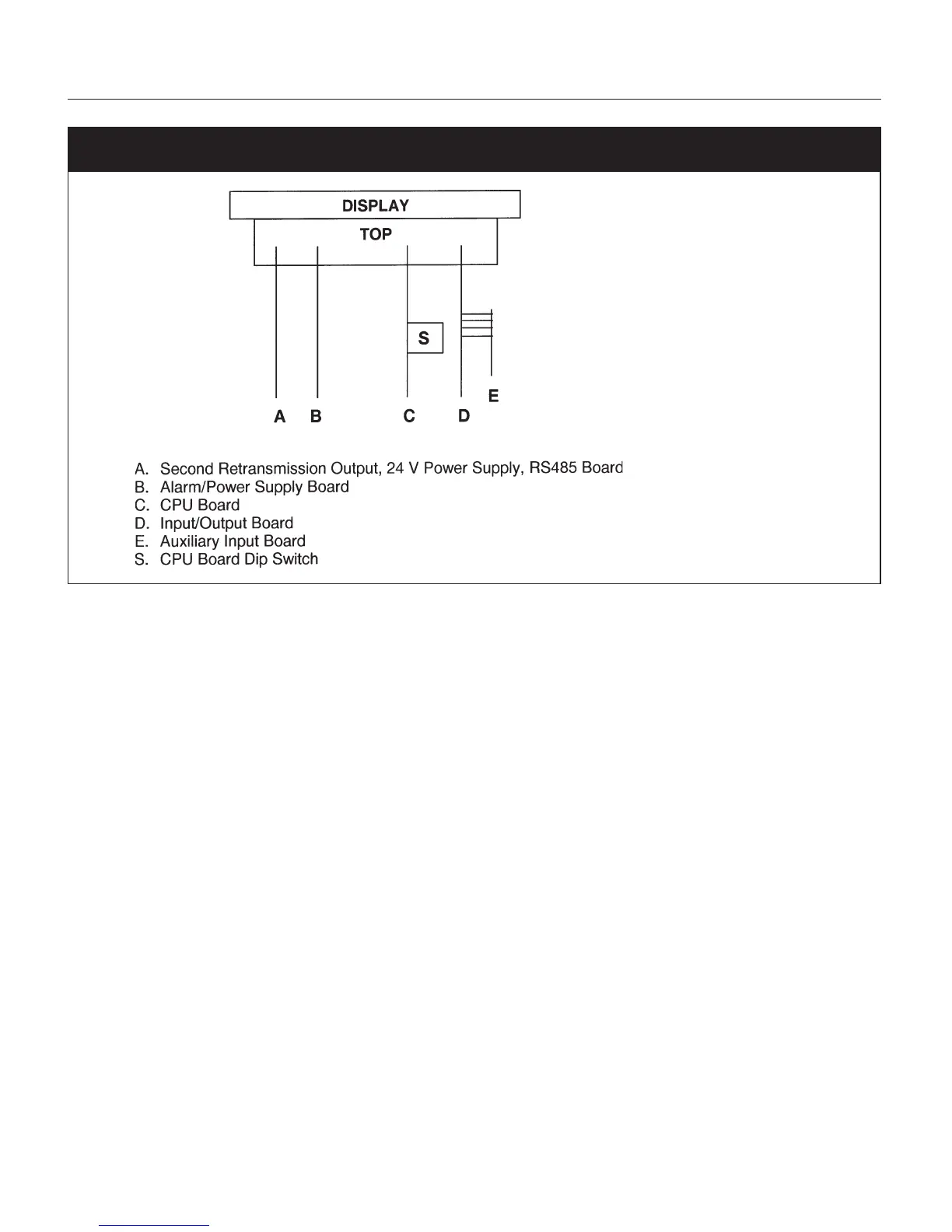
Fig. 14 UPR700 Board Location
9.2.2 GENERAL CALIBRATION PROCEDURE
1. Set the dip switches to calibration mode as shown above. The upper display should show
CAL
while the lower display shows
UPR
.
2. Use the ▼ or ▲ keys to show the following functions:
•Firmware revision
• Zero input counts (ZERO)
• Pressure input counts (STR)
• Reference junction counts (RJ)
• Remote set point, linear temperature input and line resistance for RTD input (RSP.RL)
•Thermocouple and RTD input (TC.RTD)
• Digital inputs status (DIG.IN)
•Maximum Power Consumption
•Minimum Power Consumption
3. The display values for analog inputs are scaled from 0 to 25,000 counts; it is also linear for RTD
input.
4. Use the ▼ or ▲ keys to select a display value from 0 to 10 and to check the linearity of output
circuit at 0%, 10%, 90% and 100%.