8
Installation Category: II
2.3 DISPLAY SPECIFICATION
Display: LED technology, custom type.
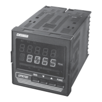
Upper Digits: Red color, 5 numeric digits, 7 segments with decimal point 13.2 mm high.
Lower Digits: Green color, 5 alphanumeric digits (British flag), 14 segments with decimal points.
12.7 mm high.
Bar Graph: Red color, 35 segment with 3% resolution. Displays continuous bar graph to indicate the
measured variable of the primary input (0-100% full scale). Alarm set point values displayed. Last
segment blinks for pressure greater than full scale value.
Indicators:
9 red LED’s annunciator for:
A1 Lit when alarm 1 is in alarm state
A2 Lit when alarm 2 is in alarm state
A3 Lit when alarm 3 is in alarm state
REM Lit when device is controlled by serial link
0-25-50-75-100-% These six LEDs are always on to improve the bar-graph indication.
2 green LED’s annunciator for:
PEAK Lit when lower display shows the peak value
TEMP Lit when lower display shows the temperature input value (only for TC and
RTD input)
2.4 PRIMARY INPUT SPECIFICATION
Primary Input: Selectable between strain gage and linear by jumper and configuration.
Strain Gage Input: 350 Ohm, 2-4 mV/V. Excitation 10 V ±7%. 6 wire connection.
Input Signal: -25/125% of full scale (approximately -10 / 50 mV).
Shunt Calibration: With or without shunt resistor (value programmable from 40.0 to 100.0%).
Zero Balance: ±25% of full scale (approximately ± 10 mV).
Linear Input: Selectable between 0-5VDC, 0-10 VDC. 0-20 mA, 4-20 mA.
Auxiliary Power supply: 24 VDC / 1.5W ± 2% power supply for two or four wire transmitter.