2-11
MODEL 424 DYNOWARE RT UPGRADE WITHOUT EDDY CURRENT
Cable Routing
Version 5 DynoWare RT Upgrade for Model 424x Dynamometers Installation Guide
REMOVING THE DYNOWARE EX CABLES
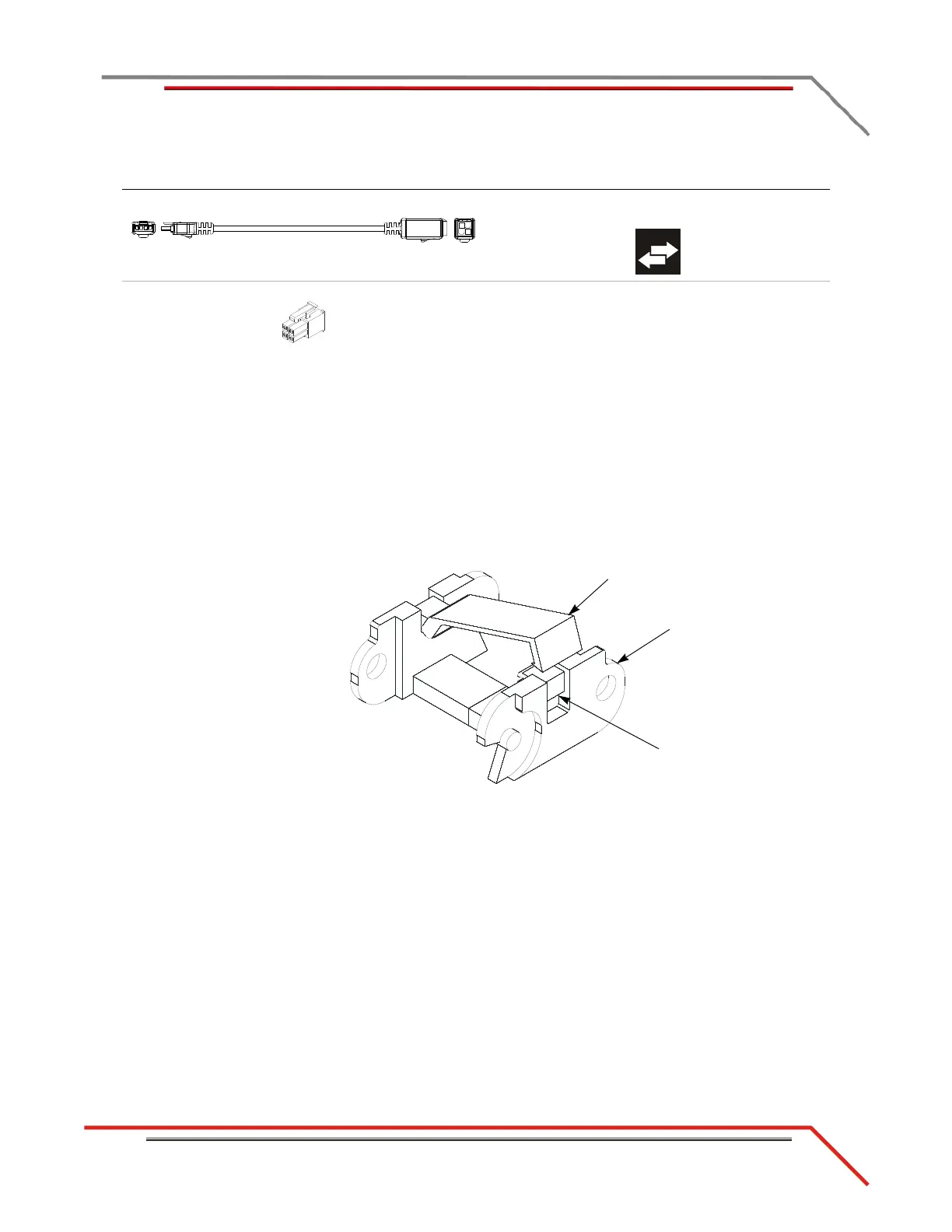
1 Remove the two 1/4-20 x 1-inch hex-head screws and two washers securing the
cable track with the signal wires to the front rail tie assembly.
Note: If your air hoses are routed through the same cable track, you will need to
disconnect them from the stationary dyno. Be sure to note or mark the air hose
positions before disconnecting the hoses. The hoses must be reconnected in the
same position.
2 Pull the cable track out from under the dyno.
3 Using a screwdriver, open the crossbar on each link.
Figure 2-9: Open the Crossbar
I - 76950807 CAN control cable, adapter, 2' connects the DynoWare RT to the CAN dyno user
cable
J - 76423045 CAN termination plug connects to the last CAN cable in the CAN network
cable chain
cable brief routing description
cable track
link
crossbar
use screwdriver
to open