DynoWare RT Upgrade for Model 424x Dynamometers Installation Guide
2-12
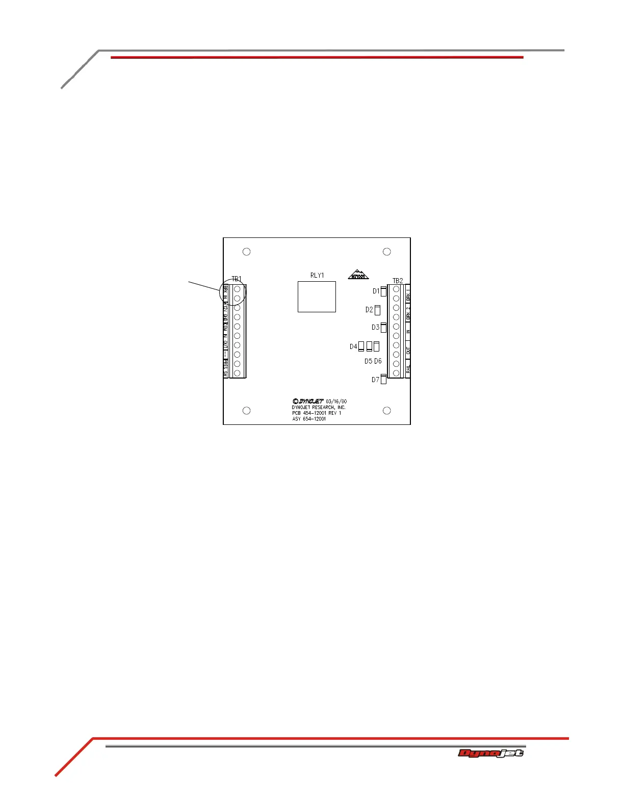
4 Disconnect the brake signal cable (twisted pair of wires) from the BRAKE
terminals on the Breakout board and the BRK IN terminals on the 4WD board.
5 Remove the brake signal cable from the cable track and discard.
6 Disconnect the 4WD dyno speed pickup cable from the DRUM 2 terminals on the
Breakout board.
7 If not already done, disconnect the 4WD dyno speed pickup cable from the pickup
card on the 4WD dyno.
8 Remove the 4WD dyno speed pickup cable from the cable track and discard.
9 Continue with “Routing the Cables” on page 2-13.
Figure 2-10: 4WD Movement Board
disconnect brake
signal wires