3-11
MODEL 424 DYNOWARE RT UPGRADE WITH EDDY CURRENT BRAKE
Remove the DynoWare EX Electronics
Version 5 DynoWare RT Upgrade for Model 424x Dynamometers Installation Guide
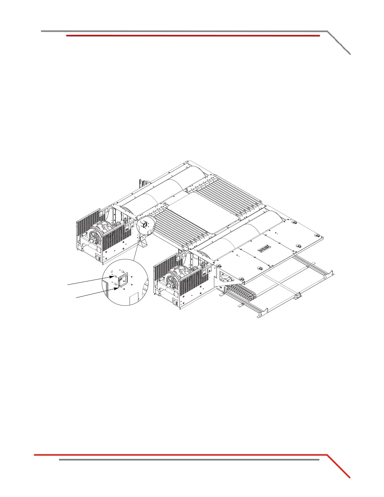
5 Disconnect the brake solenoid leads from the Breakout board. These are the black
wires running from the air solenoid to the AIR BRAKE terminals on the Breakout
board.
6 Disconnect the brake signal cable (twisted pair of wires) from the BRAKE SIGNAL
terminals on the Breakout board.
7 Disconnect the temperature sensor cables from the TEMP FROM DRUM 1 and
TEMP FROM DRUM 2 terminals on the Breakout board. Do not disconnect the
sensors from the eddy current brake.
8 Remove the four nuts securing the Breakout board to the bumpers and remove the
board.
9 Remove the four screws securing the bumpers to the dyno and remove the
bumpers.
Figure 3-7: Remove the Breakout Board