Eaton Static Transfer Switch 2000A 3-Pole Installation and Operation Manual 164001127—Rev 01 9
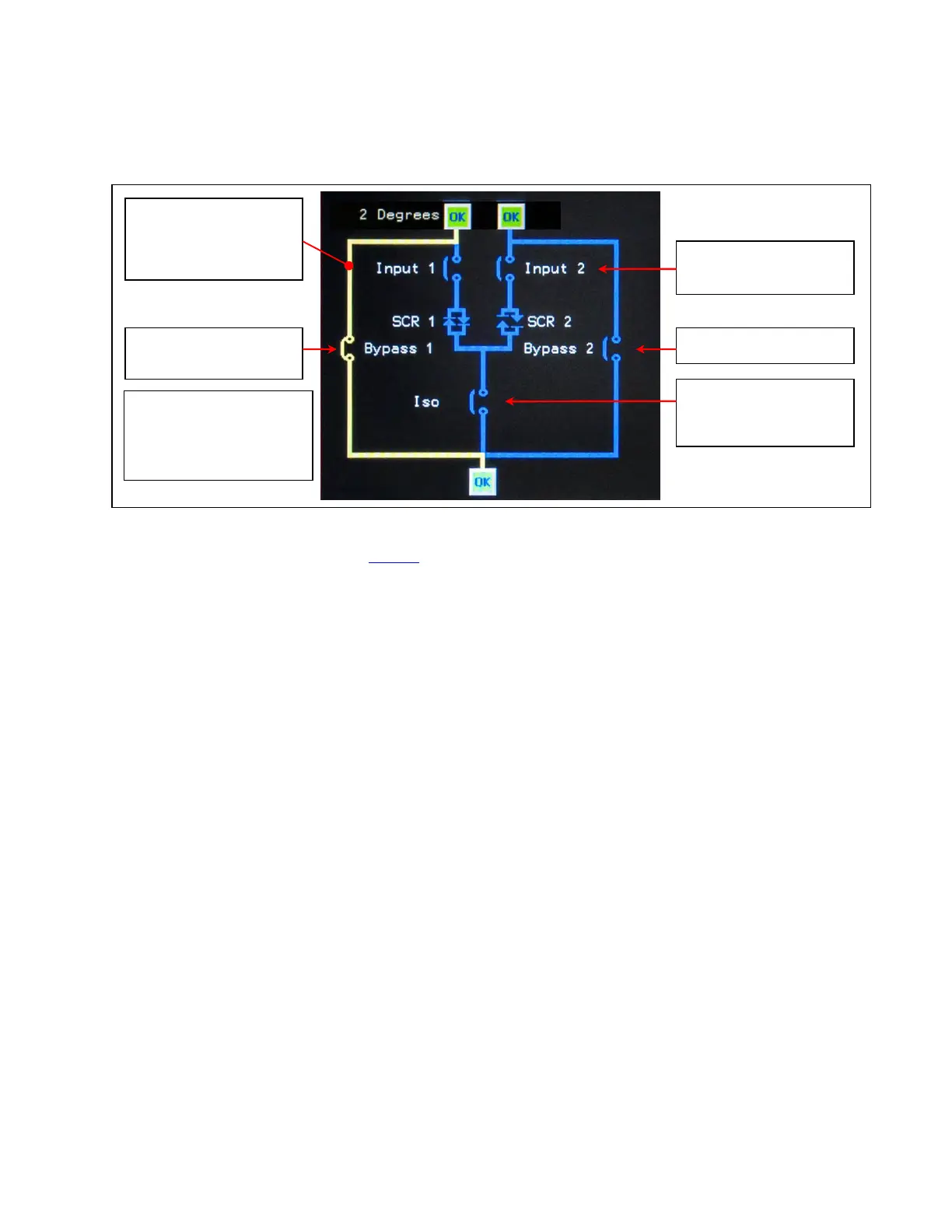
Figure 7. STS on Bypass (Bypass 1)
Source (Input) 1 and 2
MCCBs are open.
Isolation MCSW 1 is
open.
Bypass MCCB 2 is open. Bypass 1 MCCB is
closed.
STS is on Bypass 1.
Bypass 1 is the active
power path (yellow).
When the STS is on
Bypass 2,
-Bypass 1 MCCB is open.
-Bypass 2 MCCB is closed.
One-line Diagram is
from the Home screen.
In Bypass Mode operation (Figure 7), operators isolate logic and power components for maintenance by
changing the open/closed MCCB and MCSW states. Kirk Keys enforce correct coordination between breakers,
preventing cross-currents between sides.
11..55 HHiigghh AAvvaaiillaabbiilliittyy tthhrroouugghh RReedduunnddaannccyy
To keep a mission-critical load continuously supplied with power, the STS must itself be continuously
operational. To the fullest extent practical, the STS 2000A employs redundant circuits and components to
eliminate single points of failure.
• The STS is designed for an MTBF exceeding 2,000,000 hours.
• The STS has dynamic tri-redundant logic with voting circuits. Each level monitors the power beings
applied to the load, if one level does not transfer the load in specified times, the second level will transfer
the load within the CBEMA/ITS curve.
• The STS has quad-redundant gate drivers, redundant drivers for each set of SCRs. The drivers can not
inhibit or out vote the other. Therefore, both source 1 and source 2 SCRs have two levels of isolated,
independent gate drivers.
• The STS has tri-redundant logic power supplies. The configuration of each DC logic power supply is
such that a short circuit on one PCB cannot prevent the other PCBs from receiving tri-redundant power.
Each PCB receives logic power via three isolated connectors.
• The STS has N+3 fan redundancy for forced air-cooling of the SCRs.
• The STS uses tri-redundant fiber optic lite pipes and circular redundant CAN Bus to route logic signals
between logic PCBs.
• Noise immune signal buses: the STS uses optical buses and/or CAN buses to route signals between
logic PCBs.
– All signal buses are tri-redundant.
System Description