Eaton Static Transfer Switch 2000A 3-Pole Installation and Operation Manual 164001127—Rev 01 65
CChhaapptteerr 1122 SSttaattuuss,, AAllaarrmmss,, aanndd OOtthheerr DDiiaaggnnoossttiicc IInnffoorrmmaattiioonn
1122..11 PPooiinnttss LLiissttss
The STS has two points lists (Modbus Register Maps):
• Digital Points, listed in 16.1 Digital Screen Points.
• Analog Points, listed in 16.2 Analog Screen Points.
These are replicated in the Digital Values and Analog Values screens.
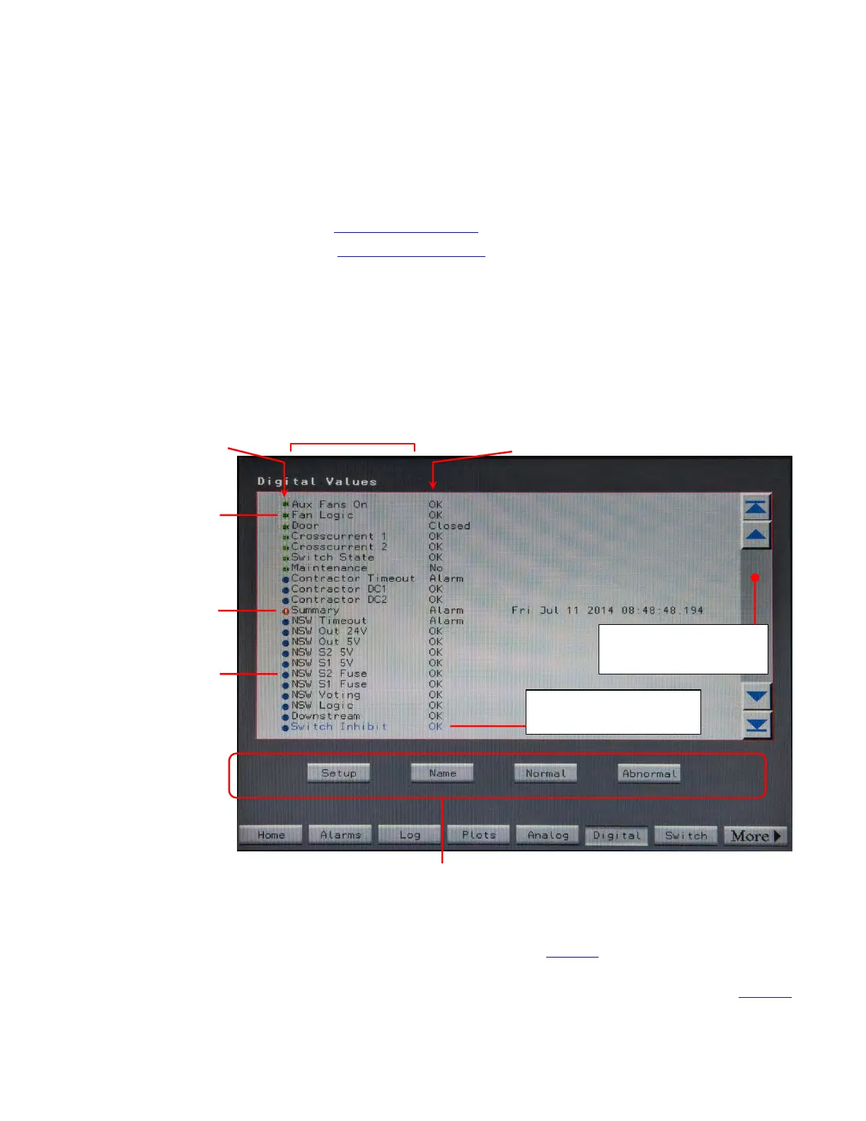
1122..11..11 DDiiggiittaall VVaalluueess SSccrreeeenn
Touch the Digital button in the navigation buttons to display the Digital screen.
Figure 28. Digital Values Screen
Blue dot is for
status points,
not defined as
alarm points.
Green dot
OK.
means point is
Red dot means
point is in alarm
condition.
Black dot (not
shown) means
point is not used or
is invalid for this
STS
implementation.
Scroll through Digital
Points using scroll bar.
The point you have
scrolled to is highlighted.
Digital Point
Status Indicator
Digital Point Status
Digital Point Name
You can change digital point parameters for the highlighted point using these buttons under
Administrator or other higher access authority. You can also change the name of a point
and change what is the normal or abnormal state, thus changing the trigger for an alarm.
The Digital screen displays the Digital Values screen as shown in Figure 28.
• The first column is the description of the digital point value’s alarm or abnormal state. Their dot indicator at
the beginning of each row indicating the general state of point (for explanation of indicator, see Figure 28).