Eaton Static Transfer Switch 2000A 3-Pole Installation and Operation Manual 164001127—Rev 01 29
CChhaapptteerr 66 CCuussttoommeerr CCoommmmuunniiccaattiioonnss CCoonnnneeccttiioonnss
Customers establish communications with the STS 2000A through these connections:
• • Ethernet connection, supporting several protocols and STS features
• • Contractor Board connections, including:
– Dry contact signals
– Modbus RTU
– Modem landline (9600 baud dial) for summary alarm notification
– Multi-Switch Link Option, supporting an N+1 UPS configuration
All communications protocols and options can be used simultaneously.
66..11 CCoonnttrraaccttoorr BBooaarrddss
Customer connections are made through either of two PCBs, a Basic Contractor Board or an Enhanced
Contractor Board, providing connection points for dry contacts, communications ports, and Remote EPO.
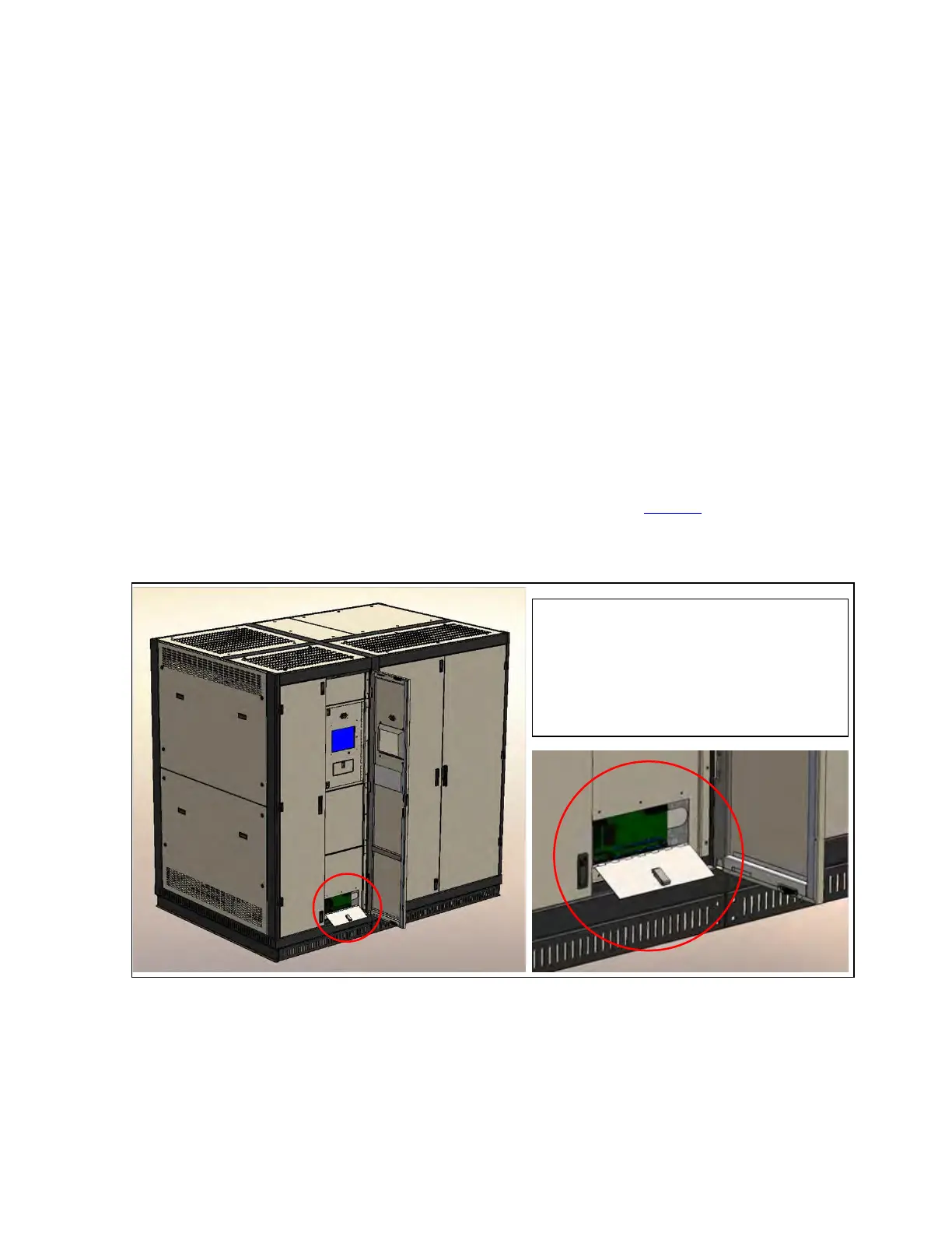
The Contractor Board is installed near the base of the STS, attached to an interior front enclosure panel behind
the locked outer doors and accessible through its own small panel door (Figure 10).
Figure 10. Figure 10 Contractor Board Access
The Contractor Board (Basic or Enhanced) is
installed in a protected enclosure that is
attached to the rear of an interior front panel.
For making or changing connections, access
the Contractor Board through its own front
panel door.
The following sections describe the formats of the Basic and Enhanced Contractor Boards.