66 Eaton Static Transfer Switch 2000A 3-Pole Installation and Operation Manual 164001127—Rev 01
• The second column describes the status of the alarm or abnormal state listed in the first column.
• The third column is the date/time stamp of when the alarm or abnormal state occurred.
1122..11..22 AAnnaalloogg VVaalluueess ssccrreeeenn
Touch the Analog button in the navigation buttons to display the Analog Values screen as shown in Figure 29.
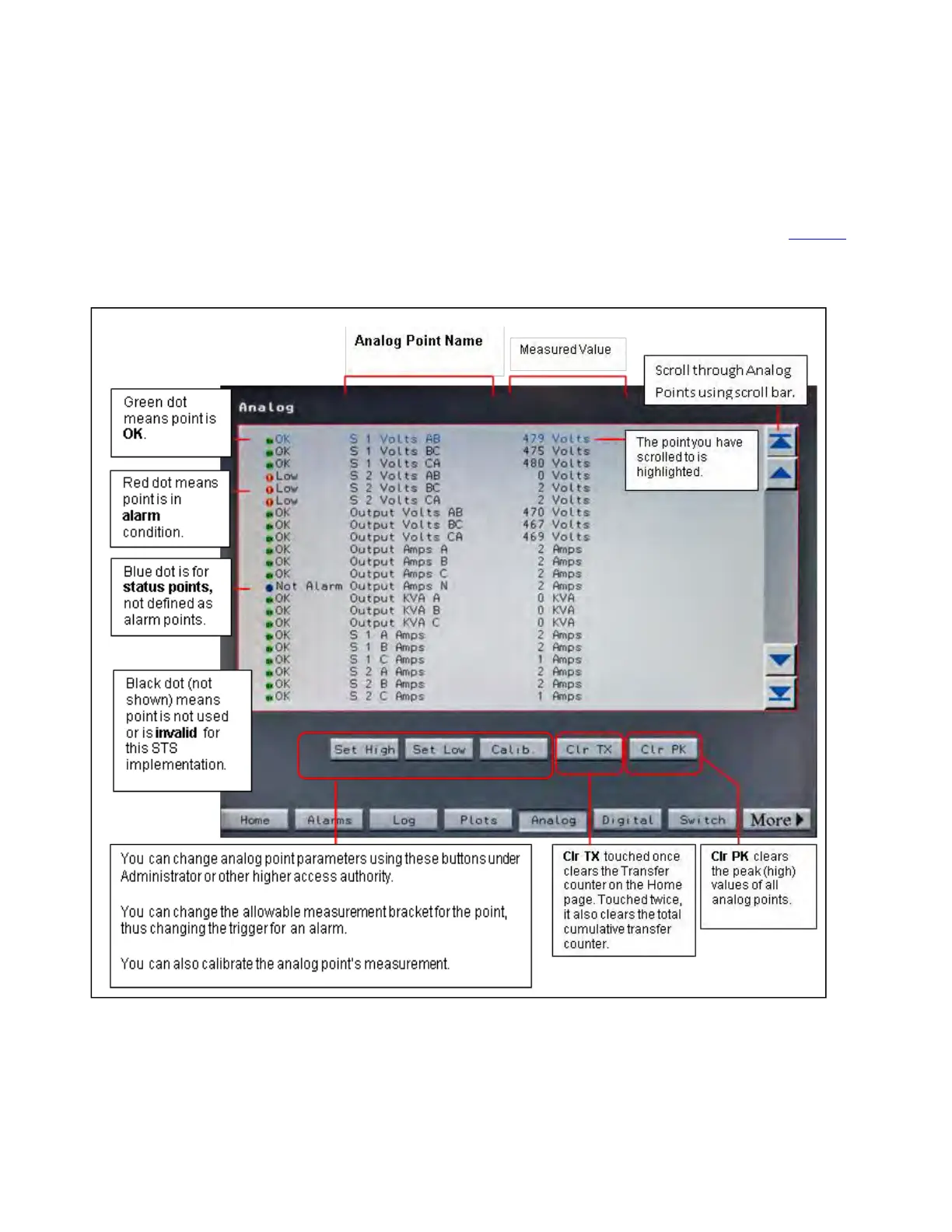
Figure 29. Analog Values Screen
Each row displays an analog point with its status and last measurement. The dot indicators at the beginning of
each row indicate the status of the point:
Status, Alarms, and Other Diagnostic Information