5. External connections
5.7 PROFIBUS interface
5.7.0.2 Profibus topology
l A bus segment can interconnect up to 32 slaves.
l Several bus segments can be connected using repeaters (bi-directional amplifiers).
The use of repeaters enables the maximum cable length to be
increased.
For more details, please consult the documentation for repeaters
provided by manufacturer.
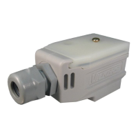
Only use bus connector plugs specified for use with PROFIBUS networks.
These plugs combine both bus cables on a node and ensure that the cable shield has a
low-impedance connection to the node's shield reference potential.
In addition, these bus connector plugs include a PROFIBUS-specific cable ter-
minationthat can be activated if necessary.
A bus segment must be provided with cable termination at both ends. This termination
is passive, but is fed from the node. It ensures a defined quiescent state on the bus if no
bus station is sending. These bus terminations are preferably implemented externally in
the connector housing as per the PROFIBUS standard (and can be implemented using
the aforementioned bus connector plugs).
1
2
3
6
7
5
4
8
9
390
390
1
2
3
6
7
5
4
8
9
1
2
3
6
7
5
4
8
9
1
2
3
6
7
5
4
8
9
M5EXT
(GND)
A
B
M5EXT
(GND)
A
B
M5EXT
(GND)
A
B
M5EXT
(GND)
A
B
M5EXT
(GND)
A
B
M5EXT
(GND)
A
B
220
220
390
390
Figure 35: Profibus bus segment with four nodes
l The bus segment must be terminated at both ends.
l No more than two terminations must be provided for each bus
segment.
l At least one of the two terminations must be fed by the bus user.
l Operation without correct termination of the Profibus network can
cause transmission errors.
XV30004/19 MN048017ENwww.eaton.eu
67

 Loading...
