F9 Fetal & maternal Monitor Service Manual Principle Introduction
- 27 -
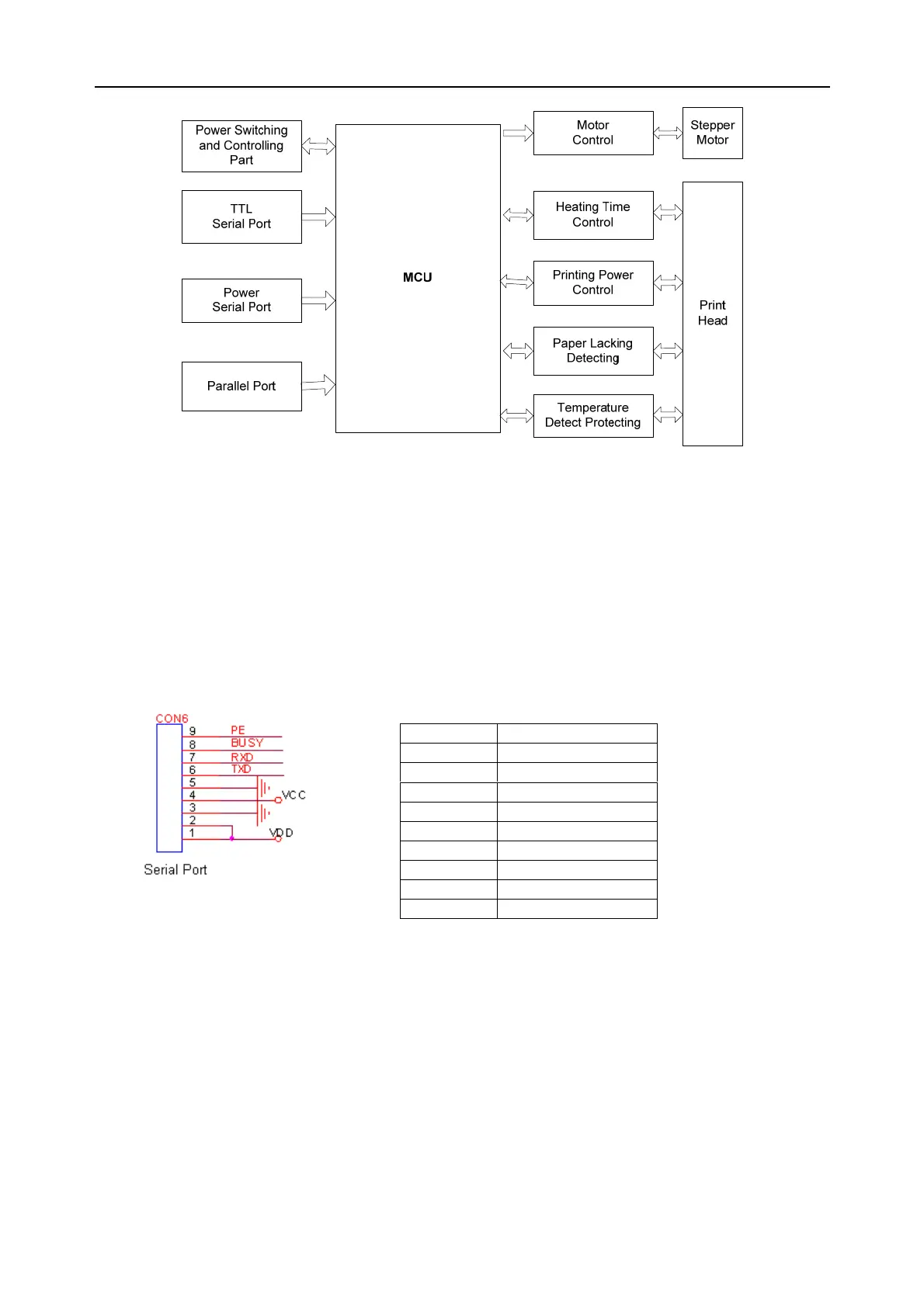
Figure 7-4 Print controlling board principle block diagram
The F9 recorder module includes: microprocessor MC9S12A64 circuit, power switch and control,
communicate interface, motor control part, recorder paper detecting circuit, time control for
printing power and heating, paper lacking temperature control and thermosensitive head
protecting circuit.
Definitions of print controlling board interfaces
(1) Interface connects to bottom interface board
Pin No. Symbol
1 VDD
2 VDD
3 GND
4 VCC
5 GND
6 TXD
7 RXD
8 BUSY
9 PE
 Loading...