F9 Fetal & maternal Monitor Service Manual Modules’ Malfunction Verification
- 40 -
Chapter 9 Modules’ Malfunction Verification
When a module is suspected of malfunction, verify it using the method described in this chapter.
NOTE: For all the interfaces, the first pin is the one with a square solder pad.
9.1 Verifying Malfunction of the Main Control Board
To verify the main control board,
1)
Open the main unit using the procedures described in section 10.3.
2)
Switch on the monitor. (Powered by AC or battery.)
3)
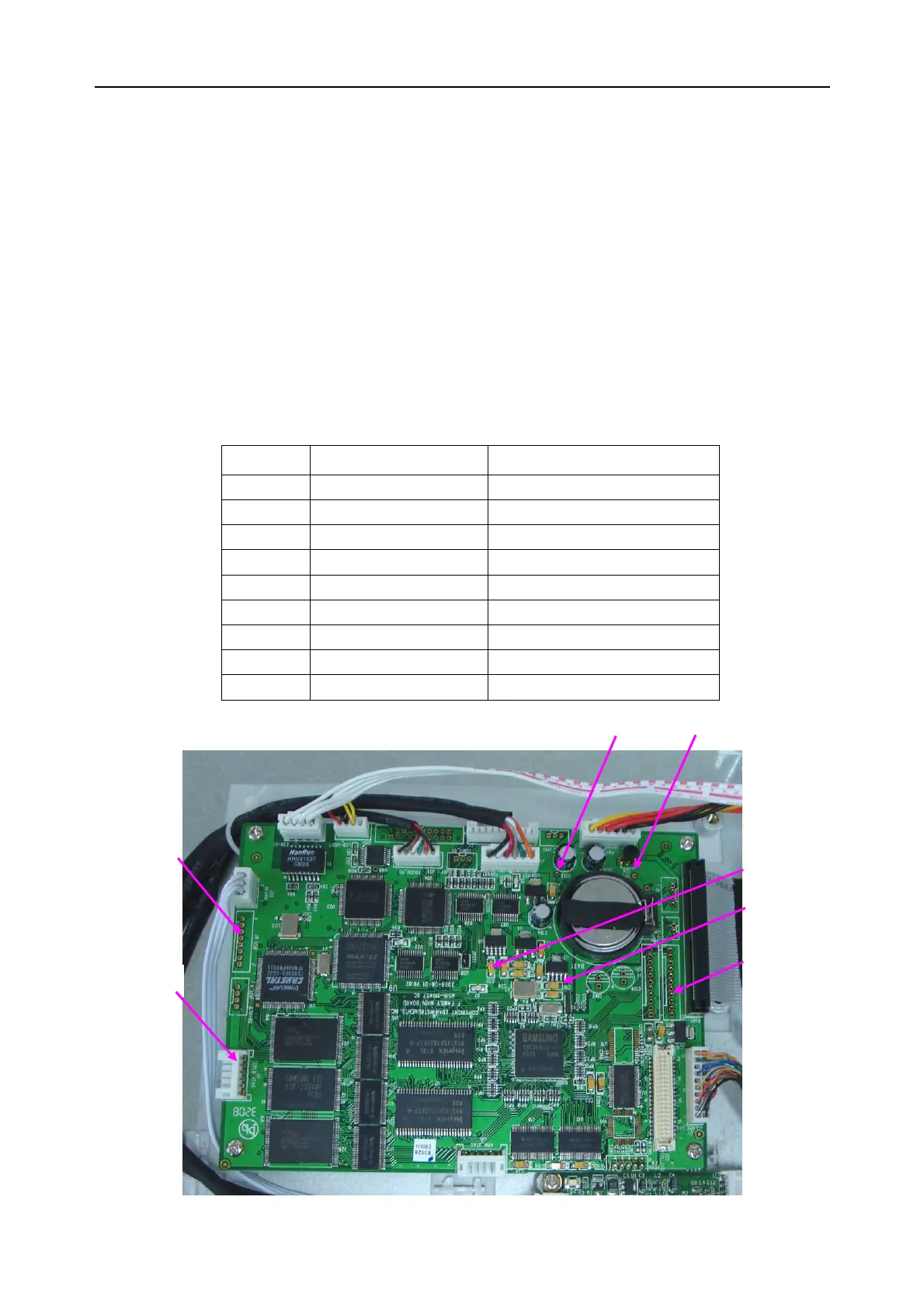
Measure the voltage to earth of the pins listed below, using a multimeter:
Item Pin Reference result
○
1
J8’s first pin VCC+5V (5.0±5%) V
○
2
J31’s first pin
VCC33(3.3±5%)V
○
3
TP1 +12V (12.0±5%) V
○
4
TP2
PVCC(3.3±5%)V
○
5
C35’s positive pole VDDARM (1.9±5%) V
○
6
C16’s positive pole VDDALIVE (1.9±5%) V
○
7
J2’s first pin VBB33 (3.3±5%) V
○
8
C59 VDD_RTC (1.8±5%) V
○
9
C61 Li_BAT (≥2.75V)
○
3
TP1 ○
4
TP2
Main control board
○
2
J31
○
5
C35
○
6
C16
○
7
J2
○
1
J8