F9 Fetal & maternal Monitor Service Manual Modules’ Malfunction Verification
- 45 -
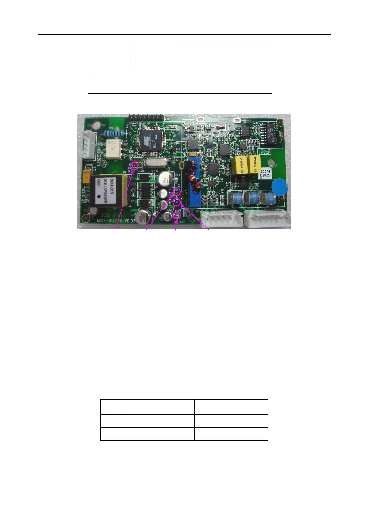
Item Pin Reference result
○
4
TP7 (+3.3±5%) V
○
5
TP5 (+8±5%) V
○
6
TP6 (-8±5%) V
○
7
T1 (+5±5%) V
7)
Compare the measurement results with the reference results in the list. If any one of the
results exceeds the reference range, the DECG module defection is confirmed. Replacement
of the module is recommended.
9.4 Verifying Malfunction of the Power Module
To verify the power module,
1)
Open the main unit using the procedures described in section 10.3.
2)
Disconnect the power board connector from the bottom interfaces board.
3)
Switch on the monitor.
4)
Measure the voltage to earth of the following pins on the bottom interface board, using a
multimeter: (Refer to section 9.3 for J3’s location.)
Item Pin Reference result
○
1
1
st
pin of J3 (+5±5%) V
○
2
5
th
pin of J3
(+12±5%) V
5) If any one of the results exceeds the reference range, the power module defection is
confirmed. Replacement of the module is recommended.
○
4
TP7 ○
5
TP5 ○
6
TP6 ○
7
T1
DECG Board

 Loading...