F9 Fetal & maternal Monitor Service Manual Principle Introduction
- 30 -
7.2.7 Bottom Interfaces Board
F9 bottom interfaces board consists of connect CNS interconnection circuit, voltage switching
circuit, built-in wireless module power circuit and interfaces.
Interface definition
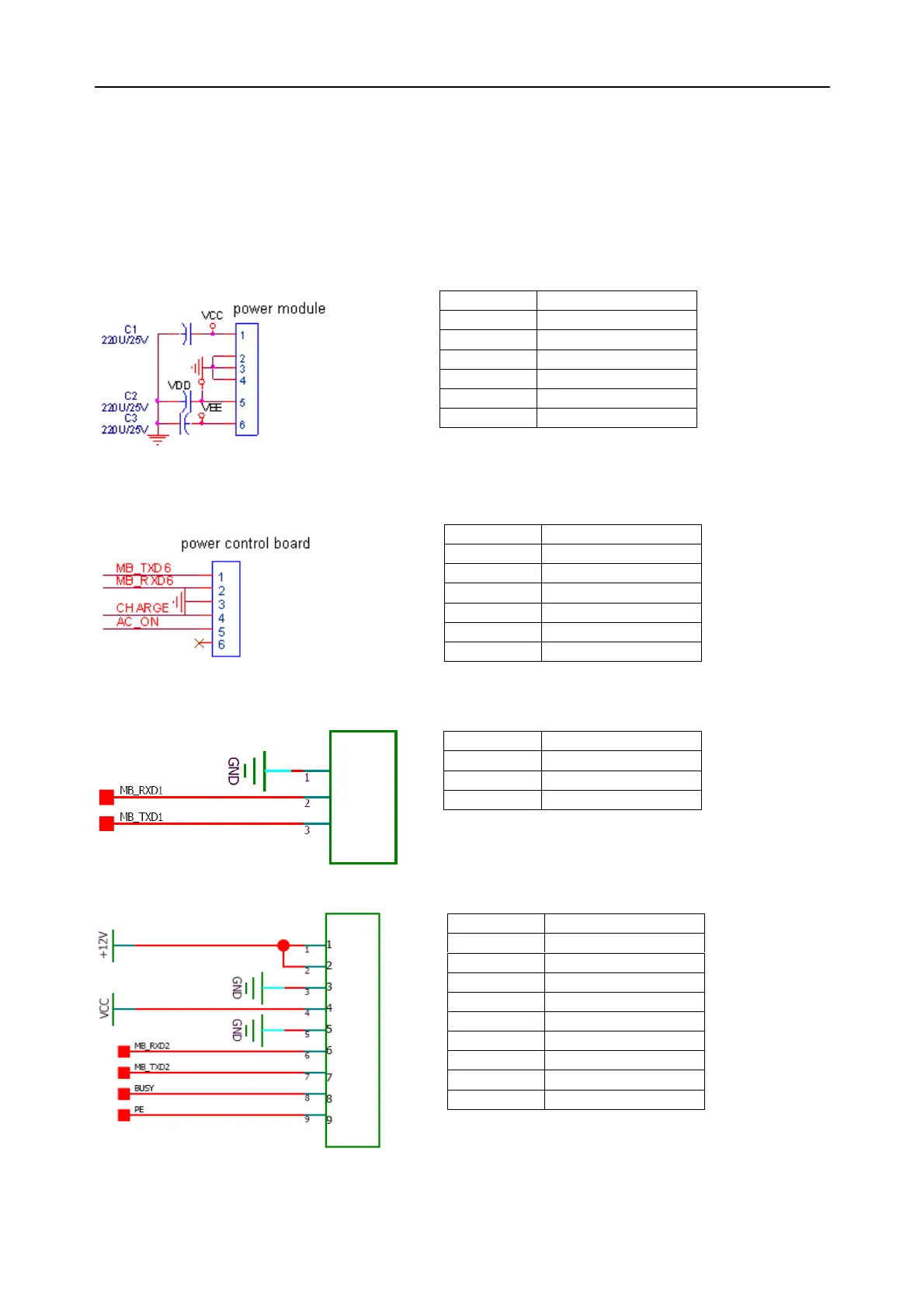
(1) Interface connects to PS800B power module
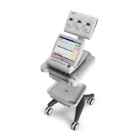
(2) Interface connects to power control board
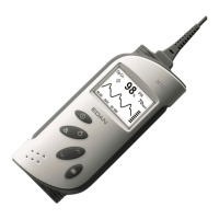
(3) Interface connects to FM board
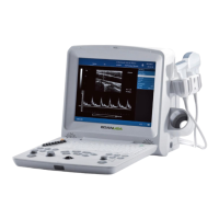
(4) Interface connects to print controlling board
Pin No. Symbol
1 VCC
2 GND
3 GND
4 GND
5 VDD
6 VEE
Pin No. Symbol
1 MB_TXD6
2 MB_RXD6
3 GND
4 CHARGE
5 AC_ON
6 Reserved
Pin No. Symbol
1 GND
2 MB_RXD1
3 MB_TXD1
Pin No. Symbol
1 +12V
2 +12V
3 GND
4 VCC
5 GND
6 MB_RXD2
7 MB_TXD2
8 BUSY
9 PE