F9 Fetal & maternal Monitor Service Manual Principle Introduction
- 28 -
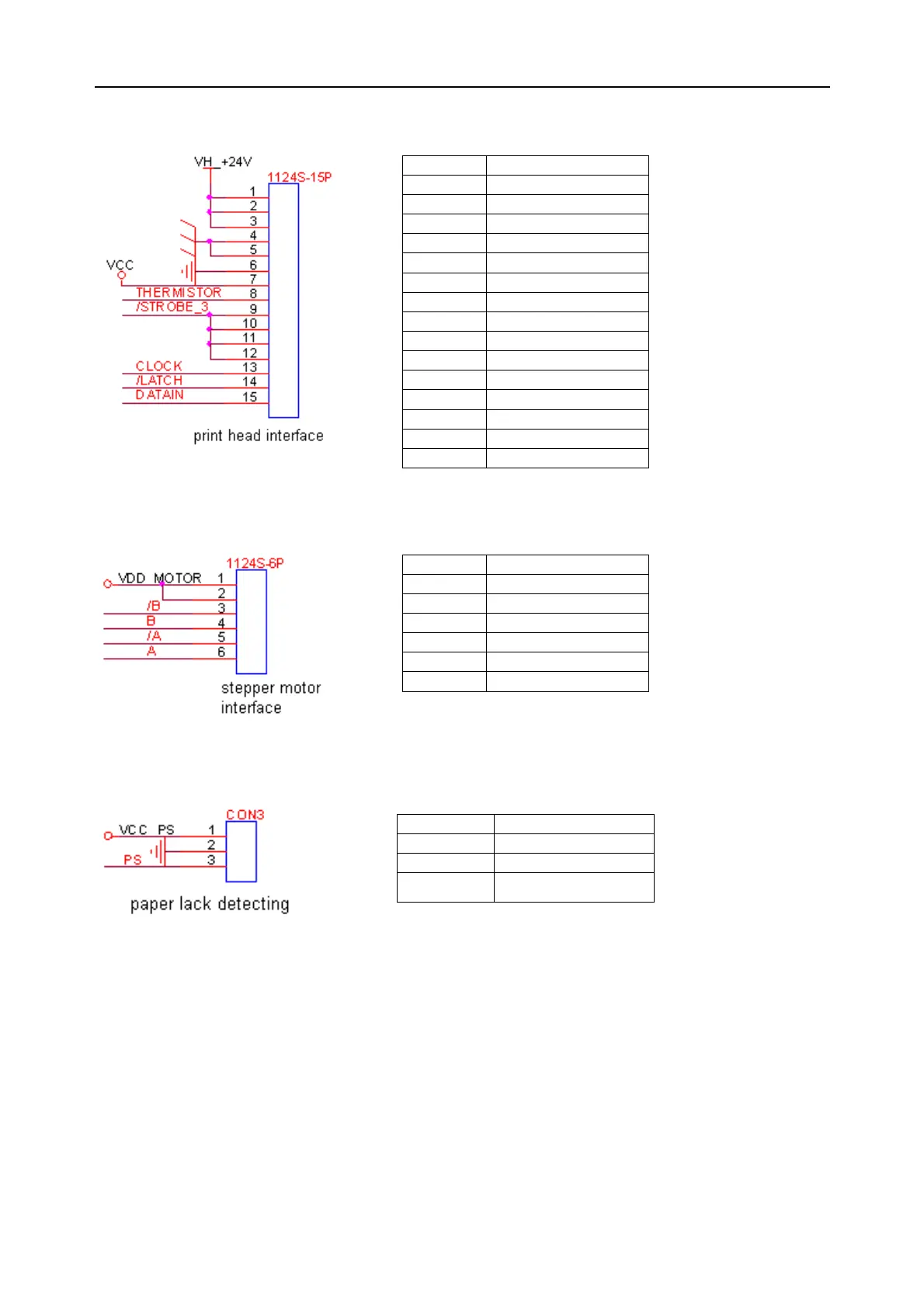
(2) Interface connects to print head
(3) Interface connects to stepper motor (gear assembly)
(4) Interface connects to paper sensor (paper lack detecting)
7.2.5 Power Module
The power module outputs +12V, -12V, +5V voltage and manages charging.
The power interface board is used to transfer the power, its circuit is:
Pin No. Symbol
1 VH_+24V
2 VH_+24V
3 VH_+24V
4 GND
5 GND
6 GND
7 VCC
8 THERMISTOR
9 /STROBE_3
10 /STROBE_3
11 /STROBE_3
12 /STROBE_3
13 CLOCK
14 /LATCH
15 DATAIN
Pin No. Symbol
1 VDD_MOTOR
2 VDD_MOTOR
3 /B
4 B
5 /A
6 A
Pin No. Symbol
1 VDD_PS
2 GND
3 PS