Vital Signs Monitor Service Manual Test and Maintenance
- 22 -
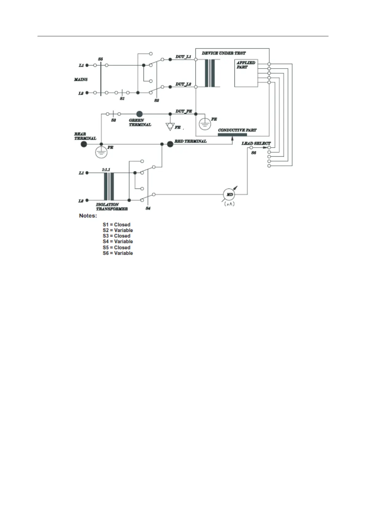
NOTE:
The circuit diagram is based on the Fluke 601Pro series safety Analyzer.
This test measure the current flowing between the applied part and the mains PE in response to an
isolate mains voltage (110% of the mains voltage) applied to applied part. This test is performed
with normal and reverse polarity of the mains voltage using S2, and normal and reverse polarity
of the isolate voltage using S4.
Single fault condition: S1, S3, S5 closed, S2, S4, S6 variable.
Allowable value:
Single fault condition (110% mains voltage on applied part):
5000µA (BF applied part), 50µA (CF applied part)
(IEC/EN 60601-1 UL 60601-1)
4.4 Maintenance
For details about basic cleaning and maintenance methods, refer to relevant sections in iM3 Vital
Signs Monitor User Manual. For further technical support, contact service engineers of EDAN.
Users are responsible for preventive maintenance and periodic inspection for the monitor.