Vital Signs Monitor Service Manual System Principle
- 26 -
Chapter 6 Principle Introduction
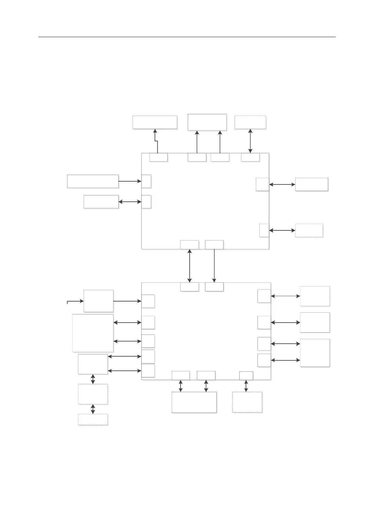
6.1 System Principle Block Diagram
The system consists of three parts: main control board, parameter board and power module.
Main control board
J3 J10 J5
Alarm indicator
board
J4
8 inch LCD
screen
Touch
screen
J8
J9 Keyboard
J12
Rotary knob board
Micro-SD
card
J6
WIFI
module
J7 J14
Parameter board
J17
AC-DC
power
board
Reachctrl
Power
J31
J30
Interface
board for
network and
USB
J25J37
J12
J22 J36
Battery,
Bluetooth board
J19
QR code
module
J8
TEMP
module
J28
J29
Pump
valve
SpO2
sensor
board
J32
Printer
switching
board
Printer
J5
SUNTECH
Figure 6-1 iM3 System Principle Block Diagram
6.1.1 Main Control Board
Using the digital platform of 9G45, the main control board achieves the machine control, display,