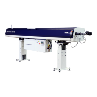
MINUTEMAN 320
6
REV 13.1:2020
2.2 Machine footprint and Installation Area
Caution machine placement is important and proper planning should
be observed. A level floor free from cracks is ideal for anchoring of the
machine. As the customer is the one that decides on machine installation
placement it is their responsibility to be aware of proper floor requirements.
Placement of the bar feeder is important to gain the use of all the features. It is important to
review the lathe layout to be sure proper clearance exists of the assembly. On some lathes
accessories may prohibit proper placement such as tool changers and transformers. On certain
lathes a “Chucker Mode” option is available. This option requires the physical movement of the
bar feeder fore and aft to the lathe headstock Z axis movement plane, while anchored to the
floor. Be sure to place the bar feeder close enough to supply the reach for the pusher when the
lathe is converted to “Chucker Mode” If placed too far the remnant will be longer than normal. Be
advised that too close may allow the bar feeder telescoping nose to collapse into the head stock
when the headstock moves to full negative over travel.
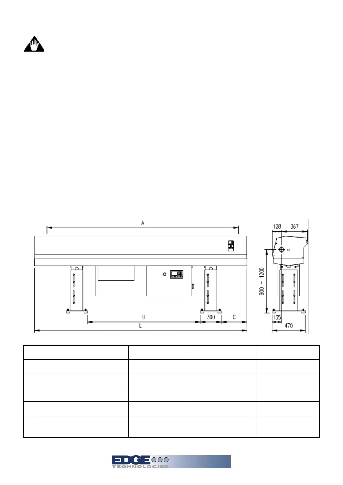
The Minuteman models are available in 4 different bar capacity configurations reflected in the
chart below.
MODEL 22 32 37 44
L
2830mm (111.4") 3870mm (152”) 4370mm (172") 4970mm (195.7")
A
2100mm (82.6") 3200mm (126”) 3800mm (149.6") 4400mm (173.2")
B
1510mm (59.4") 1810mm (71.3”) 2178mm (85.7") 2478mm (97.5")
C
345mm (13.5") 452mm (17.8”) 583mm (23") 881mm (34.7")
Weight
380 kg. (837.7lbs.)
520 kg
(1052.74 lbs.)
600 kg.
(1214.7lbs.)
680 kg.
(1376.7lbs.)