USING THE E-42B 31
• All color patches should be visible, even though they may be very faint in the 5% and 2%
range.
• Each color’s patch set should show uniform gradation from patch to patch as the color
lightens from 100% to 0%.
Poor image or color quality may indicate a need to calibrate the system or service the copier/
printer. Information on the Test Page includes the date and time of the last calibration, so the
Test Page can be kept for future reference. For more information, look up printing problems
on page 117, or see Color Printing from the user documentation set.
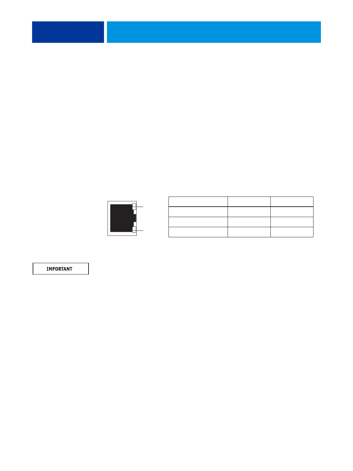
Network status LEDs
Two LEDs next to the Ethernet connector indicate the network speed. When a data transfer
occurs between the E-42B and the network, the appropriate LED(s) blink to indicate network
activity. For additional network information, see Configuration and Setup, which is part of the
user documentation set.
NOTE: Network connectivity is supported only through the upper RJ-45 port on the E-42B
connector panel. The lower port is the scan interface. The network and scan cables look
similar, but are not interchangeable. Make sure not to swap the cables. (For the correct
connections, see page 35).
Network link speed LED 1 LED 2
10 Megabits/second Off Green
100 Megabits/second Green Green
1000 Megabits/second Amber Green
LED 2
LED 1
Ethernet network port
(Upper RJ-45)