REPLACING PARTS 82
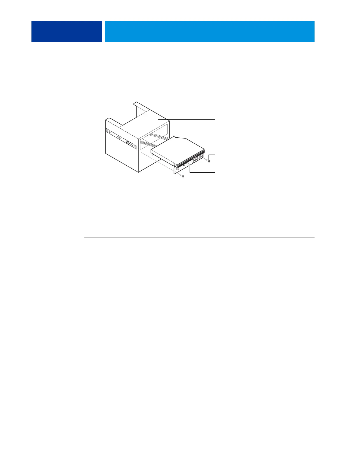
6 Remove the switch bank assembly from the component sled.
• Remove the three screws that attach the switch bank assembly to the component sled.
• Pull the switch bank assembly straight out of the component sled.
FIGURE 26: Removing/replacing the switch bank assembly
NOTE: Guide the cables as you remove the assembly from the component sled. Be careful not
to damage the EMI gasket around the opening in the component sled.
7 If you are removing the switch bank assembly to replace it with a new assembly, remove the
DVD drive (see page 84).
TO REPLACE THE SWITCH BANK ASSEMBLY
1 If it is not already attached, attach the DVD drive to the switch bank assembly
(see page 85).
2 Install the switch bank assembly in the component sled (see Figure 26).
NOTE: If you are replacing the switch bank assembly with a new one, discard the cable
extensions that may be provided with the new switch bank assembly.
• Starting with the cables, insert the switch bank assembly through the opening in the front
of the component sled. Be sure to fold the EMI gasket under and through the opening
when inserting the assembly.
• Replace the three screws that secure the switch bank assembly to the component sled.
3 Install the component sled in the chassis (see Figure 25).
• Route the cables of the switch bank assembly in through the chassis so that the cables are
within reach of their connectors on the motherboard.
• Slide the sled into the front of the chassis until the guide latches click into place.
NOTE: Be careful not to damage the EMI gasket around the slot in the chassis when installing
the component sled.
Component sled
Switch bank assembly
Screw (1 of 3)