REPLACING PARTS 38
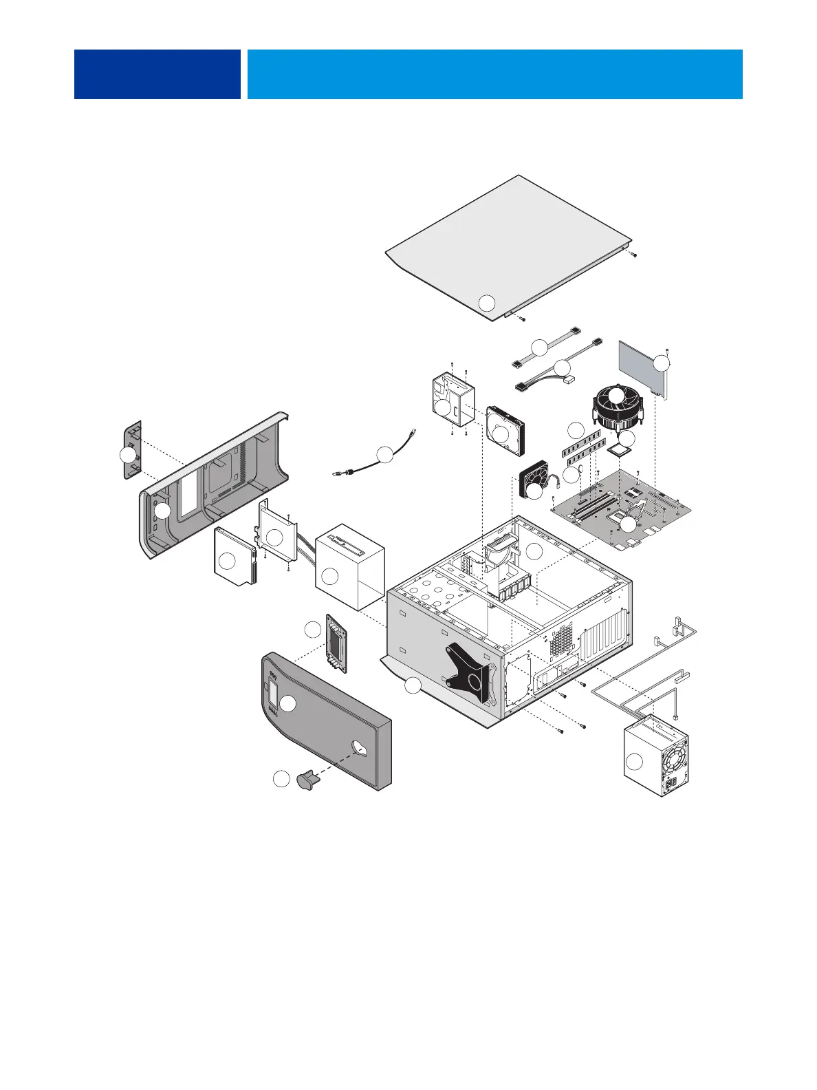
FIGURE 7: Exploded view of components
21
1
12
13
8
10
15
17
16
5
22
23
14
7
3
2
4
6
9
11
18
19
20
24
i
Key
1 Top panel plug
2 Top panel
3 User interface board (UIB)
(The UIB buttons are not included in
the user interface board spare kit.)
4 Component sled
5 Switch bank assembly
6DVD drive
7 Front panel
8 Upper faceplate
9 UIB cable
10 Hard disk drive bracket
11 Hard disk drive
12 Side panel (left)
13 Hard disk drive data cables
14 DVD drive power/data combination cable
15 CPU cooling assembly
16 Printer interface board
17 DIMMs
18 Battery
19 CPU
20 Motherboard
21 Fan
22 Chassis
23 Power supply
24 Side panel (right)