- AB620A5035 Instruction Manual
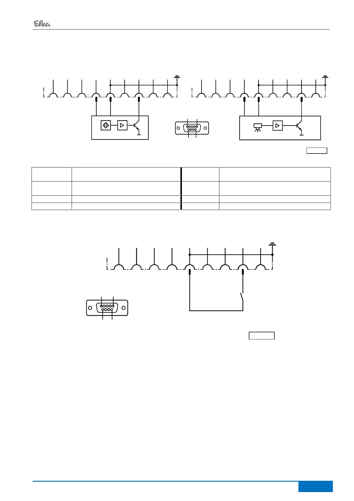
Connection of a HSM001 Hall sensor module or
an IPG001 pulse encoder
Connection of a light barrier module
LSM002
G2
OUT (4)
G2
OUT (4)
TxDTxD
SUB-D-9 (*)
RxDRxD +5V (2)+5V (2) 0V0V
G1
OUT (4)
G1
OUT (4)
POS
IN
POS
IN
LSM
IN
LSM
IN
POS2
OUT (4)
POS2
OUT (4)
5 1
9 6
B18B18
11
22
33 44 55 66
77
88 99
BI1174a
LSM002
HSM.../IPG...
Adapter cord 1113229 in case of multiple assignment of socket B18!
Possibility of connecting a light barrier
module to socket B18/8
Input for positions (e. g. connection of a
sensor)
Reflection light barrier module
Output of generator impulses
Serial transmission lines
If parameter 239 is set to >0, it is possible to operate a key at the input of the B18/8 connector.
G2
OUT (4)
TxD
SUB-D-9 (*)
RxD +5V (2) 0V
G1
OUT (4)
POS
IN
LSM
IN
POS2
OUT (4)
5 1
9
6
B18
1
2
3 4 5 6
7
8 9
BI1159a
There is a supply voltage of +5 V on the B18/4 socket for external devices. This voltage can be switched
to +15 V using parameter 362.
2) Nominal voltage +5V, I
max
100 mA (switchable to +15 V, I
max
100 mA)
4) Logic level output +5 V, I
max
5 mA
*) View: Front view of the control (component side) and/or rear view of the outgoing connecting cable