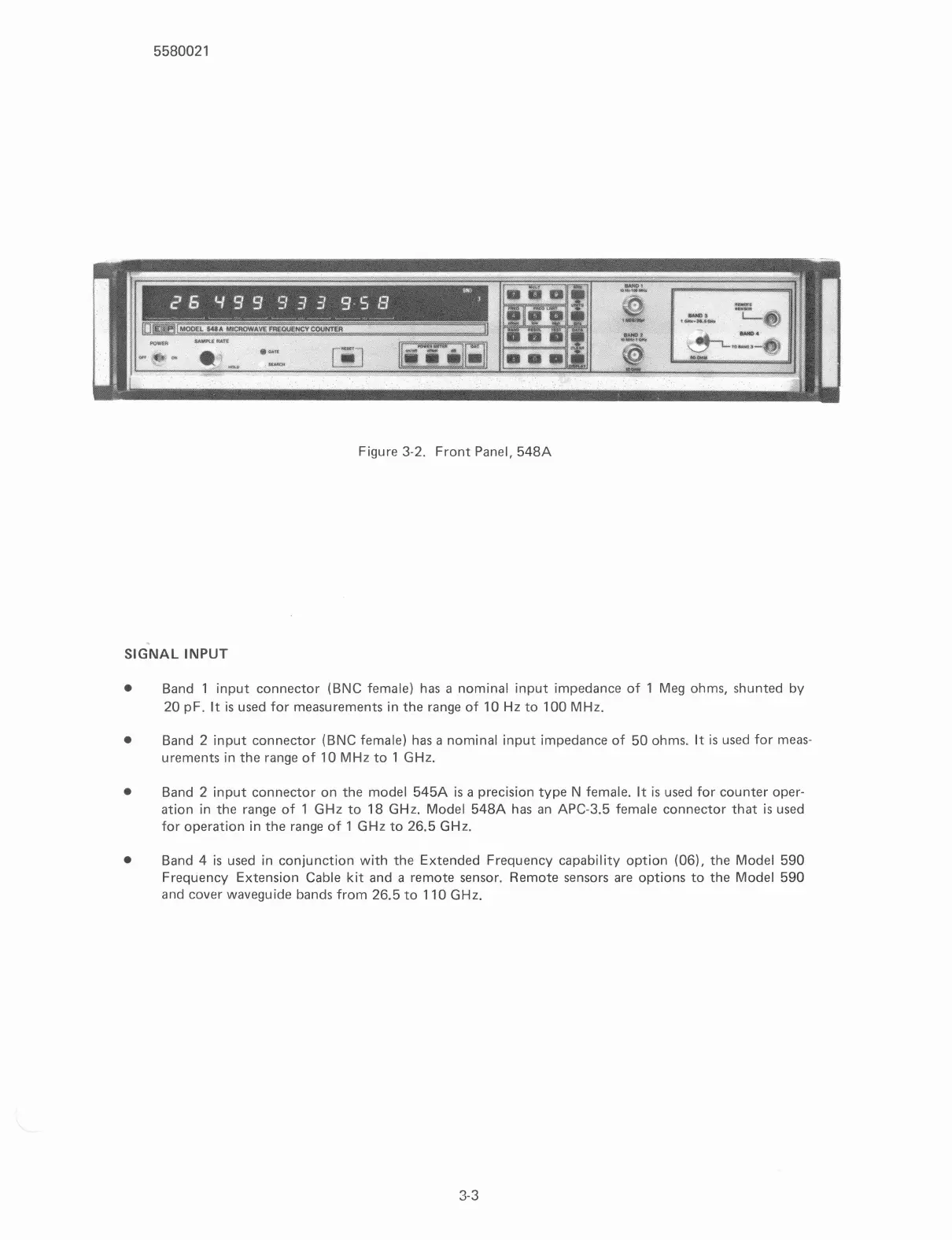
Figure
3-2.
Front Panel,
548A
SIGNAL INPUT
Band
1
input connector (BNC female) has
a
nominal input impedance of
1
Meg ohms, shunted by
20
pF.
It
is
used for measurements in the range of
10
Hz
to
100
MHz.
Band
2
input connector (BNC female) has
a
nominal input impedance of
50
ohms.
It
is used for meas-
urements in the range of
10
MHz
to
1
GHz.
Band
2
input connector on the model
545A
is
a precision type N female. It
is
used for counter oper-
ation in the range of
1
GHz
to
18
GHz.
Model
548A
has an
APC-3.5
female connector that is used
for operation in the range of
1
GHz
to
26.5
GHz.
Band
4
is
used in conjunction with the Extended Frequency capability option
(06).
the Model
590
Frequency Extension Cable kit and
a
remote sensor. Remote sensors are options to the Model
590
and cover waveguide bands from
26.5
to
110
GHz.
Scans by ArtekMedia © 2007