TROUBLESHOOTING TREES
Troubleshooting trees are intended only
as
a
guide, and do not describe every possible failure situation.
Turn power off before removing or installing any P.C. boards or connectors. If the following assemblies
are repaired or replaced, recalibration of the counter will be necessary.
A101 Power Supply
A107 Gate Generator
A108 Converter Control
A203 Converter Assembly
Do not attempt to repair or disassemble
the A203 hybrid assembly.
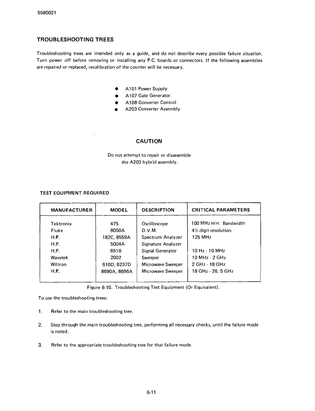
TEST EQUIPMENT REQUIRED
Figure 6-10. Troubleshooting Test Equipment (Or Equivalent).
To use the troubleshooting trees:
1.
Refer to the main troubleshooting tree.
CRITICAL PARAMETERS
100 MHz min. Bandwidth
4% digit resolution
125 MHz
10 Hz
-
10 MHz
10 MHz
-
2 GHz
2 GHz
-
18 GHz
18 GHz
-
26. 5 GHz
MANUFACTURER
Tektronix
Fluke
H.
P.
H.P.
H.P.
Wavetek
Wiltron
H.P.
2.
Step through the main troubleshooting tree, performing all necessary checks, until the failure mode
is
noted.
3.
Refer to the appropriate troubleshooting tree for that failure mode.
MODEL
475
8050A
182C. 8559A
5004A
651 B
2002
610D. 6237D
8690A, 8696A
DESCRIPTION
Oscilloscope
D.V.M.
Spectrum Analyzer
Signature Analyzer
Signal Generator
Sweeper
Microwave Sweeper
Microwave Sweeper
Scans by ArtekMedia © 2007