After pressing the first
[
,
the display will show the temporary entry, like DAC
X
,
but the three
decimal points will still show the previous DAC status.
After pressing the second
I,
the display will show the new entry, like DAC
X X
,
and the three decimal
points will move to the new places. The DAC output will start to be updated accordingly. Release of the
button pressed will return the display back to normal frequency display.
Any wrong key pressed will result in displaying ERROR 10. The operator must restart the key sequence
to enter the correct data.
CLEAR
To clear display from DAC data, ERROR display, or ignoring half-sequence entered, press
Display will return to normal and DAC status will not be changed.
DISPLAY
DAC DATA D AC
To shut off DAC press
0
or
]
CLEAR
REhllOTE OPERATION
For remote operation through GPlB refer to the GPlB (Option 08) section of this manual.
For remote operation through BCDIRMT refer to the BCDIRMT (Option
07) section of this manual.
THEORY
OF
OPERATION
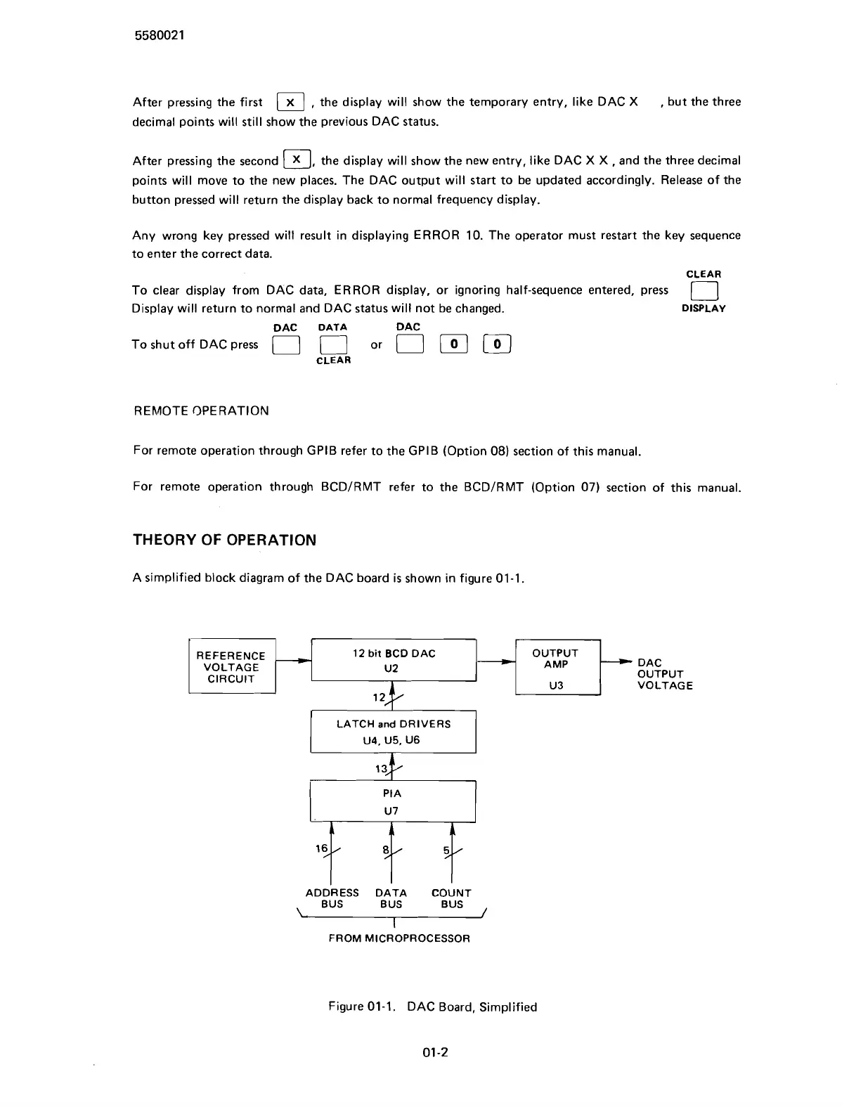
A simplified block diagram of the DAC board
is
shown in figure 01-1.
REFERENCE
12
bit
BCD DAC
VOLTAGE
ADDRESS DATA COUNT
BUS BUS BUS
,
FROM MICROPROCESSOR
Figure 01-1. DAC Board, Simplified
01
-2
Scans by ArtekMedia © 2007