OVEN OSCILLATOR CALIBRATION
When options 03,
04
or 05 are installed in the counter, the effects of temperature perturbations and aging
must
still
be considered, although the magnitude of the inaccuracies associated with each oscillator are
great1 y reduced.
Full benefit of the oven stabilized oscillator characteristics can only be realized if the oscillator
is
running
continuously (with counter always connected to
a
source of
AC
power). Under these conditions the per-
turbations in frequency will generally be in the positive direction for either an increase or decrease in
temperature from
+
25'
C.
The aging characteristic
is
also generally in the positive direction.
How frequently the oscillator
is
adjusted
is
determined by the
level
of accuracy required. To adjust the
oscillator to an inaccuracy of less than 1
X
10-9 parts, relative to
a
standard, use this procedure. The
test
is
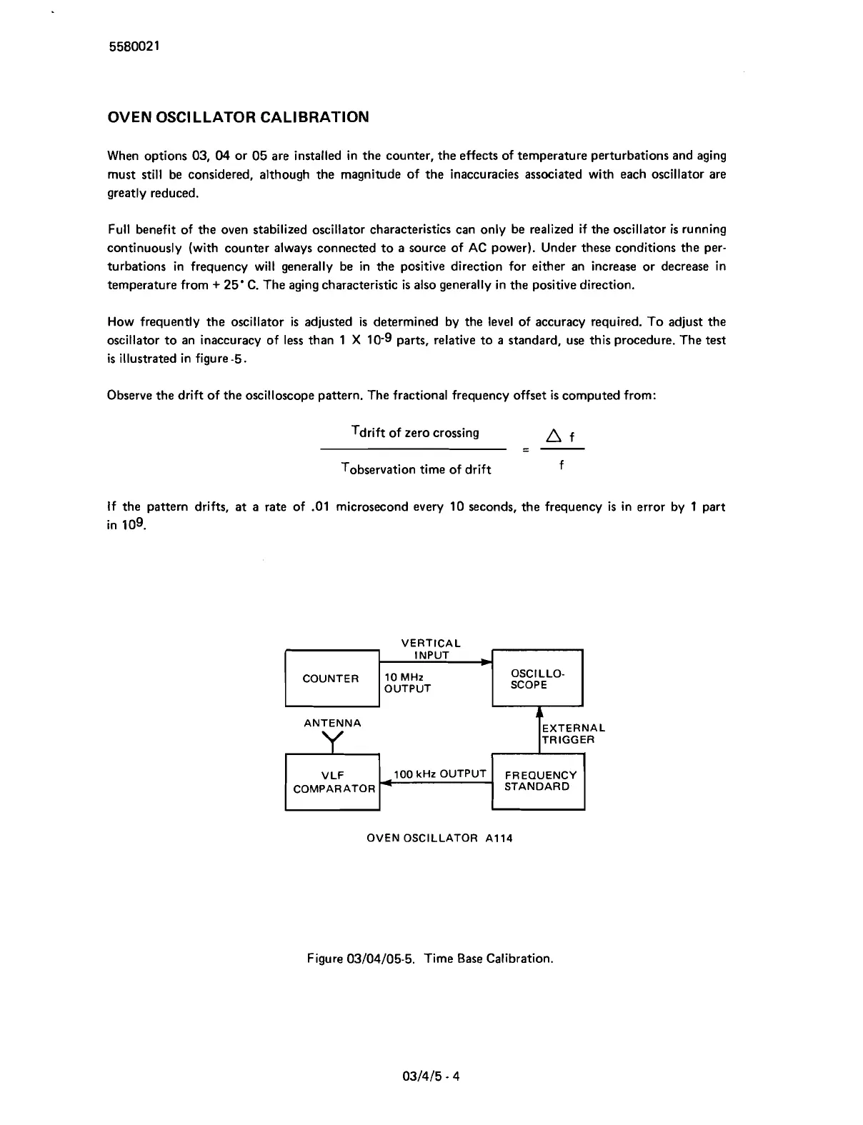
illustrated in figure -5.
Observe the drift of the oscilloscope pattern. The fractional frequency offset
is
computed from:
Tdrift of zero crossing
-
A
f
--
Tobservation time of drift f
If the pattern drifts,
at
a
rate of .O1 microsecond every 10 seconds, the frequency
is
in error by 1 part
in
109.
ANTENNA
VERTICAL
TRIGGER
-
COUNTER
OVEN OSCILLATOR A1 14
Figure 03104105-5. Time Base Calibration.
INPUT
b
10 MHz
OUTPUT
OSCILLO-
SCOPE
Scans by ArtekMedia © 2007