Section
4
Theory of Operation
GENERAL
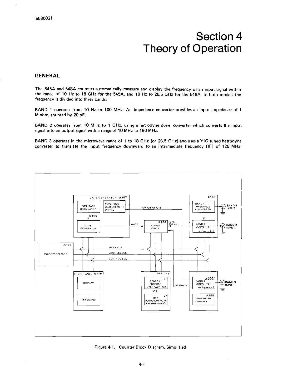
The 545A and 548A counters automatically measure and display the frequency of an input signal within
the range of 10
Hz
to 18
GHz
for the 545A, and 10
Hz
to 26.5
GHz
for the 548A. In both models the
frequency
is
divided into three bands.
BAND 1 operates from 10
Hz
to 100
MHz.
An impedance converter provides an input impedance of 1
M
ohm, shunted by 20 pF.
BAND 2 operates from 10
MHz
to 1
GHz,
using
a
hetrodyne down converter which converts the input
signal into an output signal with
a
range of 10
MHz
to 190
MHz.
BAND
3
operates in the microwave range of 1 to 18
GHz
(or 26.5
GHz)
and uses
a
YIG
tuned hetrodyne
converter to translate the input frequency downward to an intermediate frequency (IF) of 125
MHz.
I
AMPLITUDE BAND
1
BASE
MEASUREMENT DETECTOR OUT IMPEDANCE
-
BAND
1
OSCILLATOR
SYSTEM
CONVERTER
INPUT
10
MHz
GATE
A106
COUNT
&OOMHz
BAND
2
BAND
2
GENERATOR CHAIN INPUT
-
-
DATA BUS
MICROPROCESSOR
ADDRESS BUS
OPTIONS
I
PURPOSE
IPJPUT
see
figure
4
2
GATE GENERATOR A107
OUTPUTIREMOTE
PROGRAMMING
CONTROL
A109
Figure 4-1. Counter Block Diagram, Simplified
4- 1
Scans by ArtekMedia © 2007