TEST SELECTION
The following tests will verify proper operation of most functional areas of the counter. At the initial turn
on the counter performs
a
RAM and PROM check. During this check dashes are displayed until the check
has been completed.
RAM and PROM
The processor writes a sequential bit pattern to each RAM location, then independently reads that
pattern.
Thus each
bit
in each location is checked. If
the RAM check fails the display will show all
"E's". This indicates that the RAM or the RAM decoding
is
faulty.
The PROM check verifies the PROM bit pattern. If the PROM check fails an error message will be dis-
played. This indicates that the PROM's or the PROM decoding
is
faulty. See Section
6.
If both RAM and PROM check are good the counter will begin normal operation about one second after
turn on. The counter will now display
all
0's.
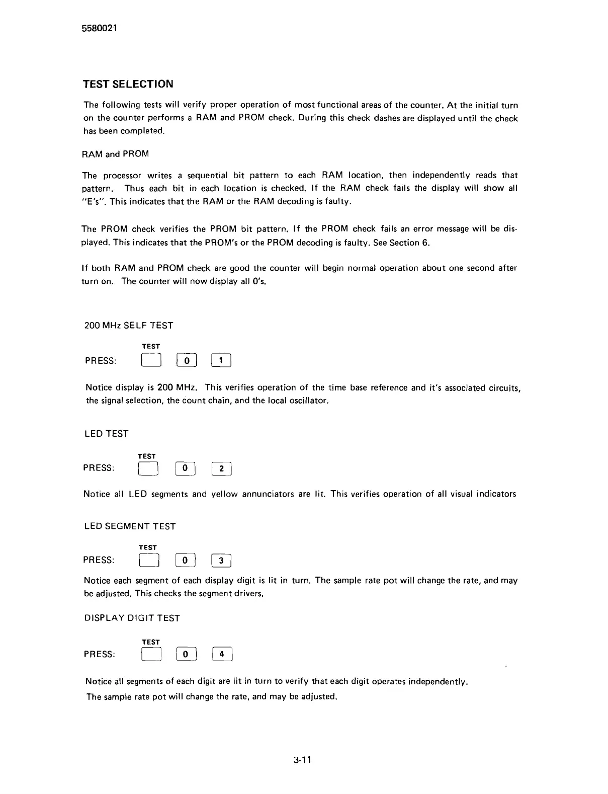
200 MHz SELF TEST
TEST
PRESS:
0
IO]
Notice display is 200 MHz. This verifies operation of the time base reference and it's associated circuits,
the signal selection, the count chain, and the local oscillator.
LED TEST
TEST
PRESS:
Notice all LED segments and yellow annunciators are lit. This verifies operation of all visual indicators
LED SEGMENT TEST
TEST
PRESS:
i,
Notice each segment of each display digit is lit in turn. The sample rate pot will change the rate, and may
be adjusted. This checks the segment drivers.
DISPLAY DIG IT TEST
PRESS:
Notice all segments of each digit are lit in turn to verify that each digit operates independently.
The sample rate pot will change the rate, and may be adjusted.
Scans by ArtekMedia © 2007