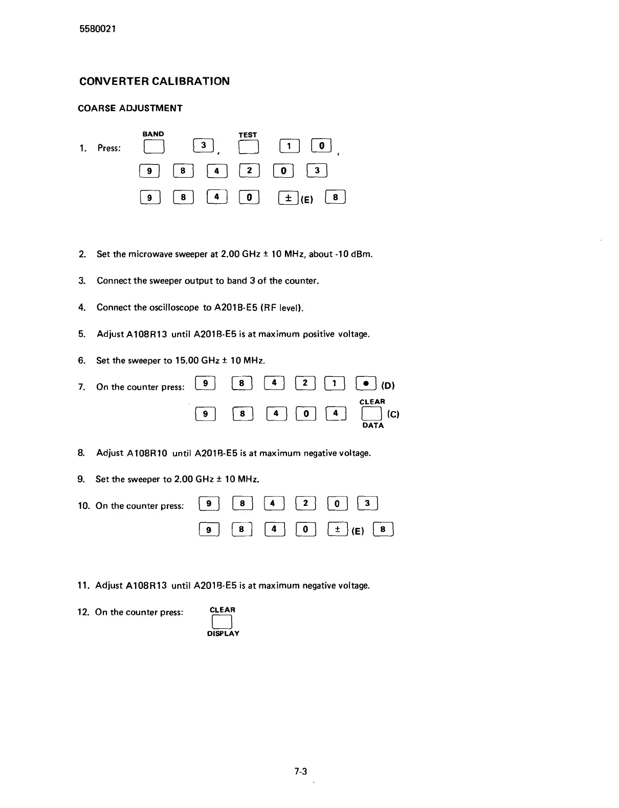
CONVERTER CALIBRATION
COARSE ADJUSTMENT
BAND
1. re:
0 0,
5
m,
El
El
m
[o]
~CE)
El
2.
Set the microwave sweeper at 2.00
GHz
+
10
MHz,
about -10 dBm.
3. Connect the sweeper output to band 3 of the counter.
4.
Connect the oscilloscope to A201B-E5
(RF
level).
5. Adjust
A108R13 until A201 B-E5
is
at maximum positive voltage.
6.
Set the sweeper to 15.00
GHz
+-
10
MHz.
7.
On the counter press:
ID)
CLEAR
P-J
(41
[o]
FJ
I-J
cc,
DATA
8.
Adjust
A108R 10 until A201 B-E5
is
at maximum negative voltage.
9.
Set the sweeper to 2.00
GHz
+
10
MHz.
lo.
On the counter press:
a
11. Adjust A108R13 until A201B-E5
is
at maximum negative voltage.
12. On the counter press:
CLEAR
0
DISPLAY
Scans by ArtekMedia © 2007