Section
7
Adjustments
and Cali
brations
GENERAL
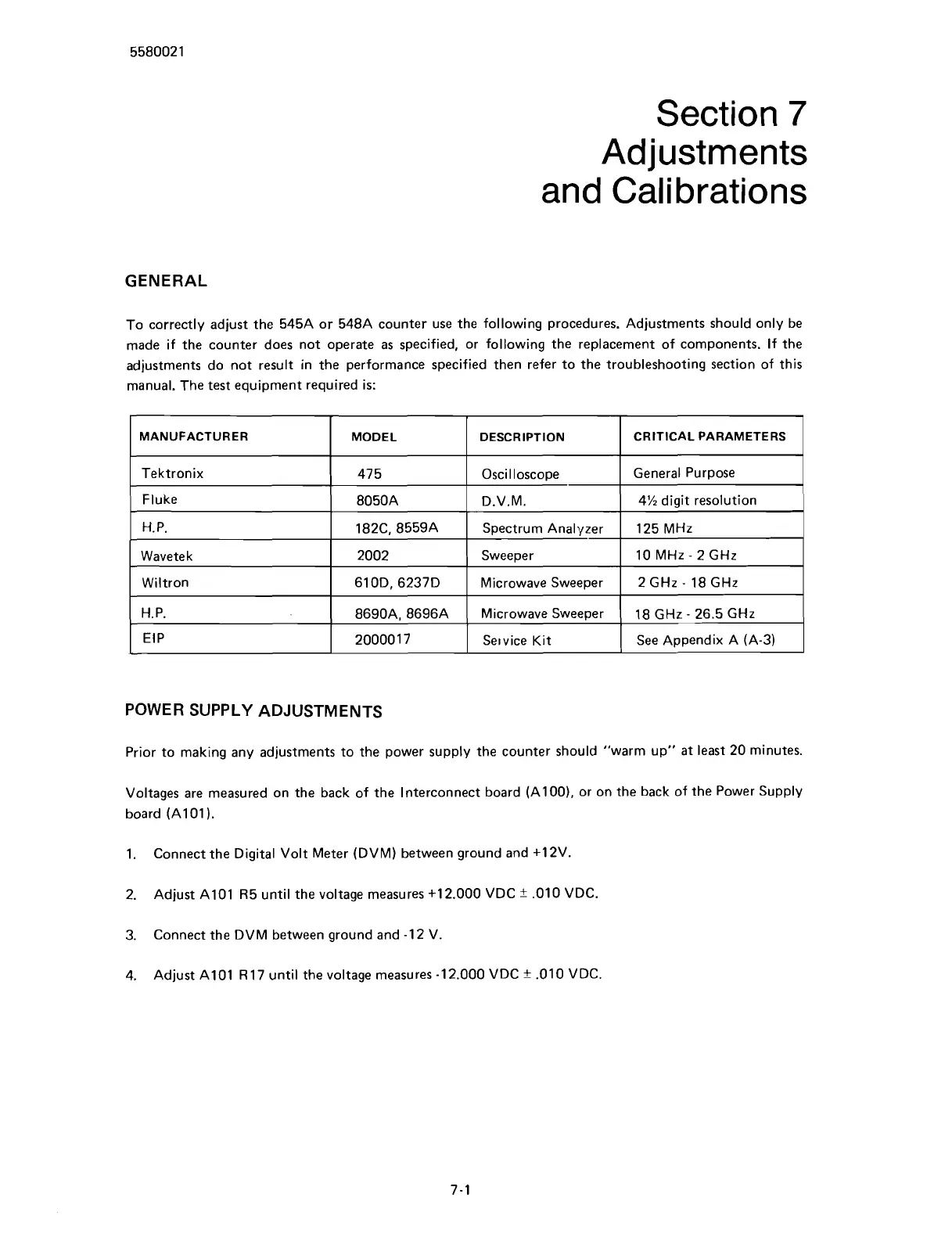
To correctly adjust the 545A or 548A counter use the following procedures. Adjustments should only be
made if the counter does not operate as specified, or following the replacement of components. If the
adjustments do not result in the performance specified then refer to the troubleshooting section of this
manual. The test equipment required is:
POWER SUPPLY ADJUSTMENTS
MANUFACTURER
Tektronix
Fluke
H.
P.
Wavetek
Wiltron
H. P.
EIP
Prior to making any adjustments to the power supply the counter should "warm up" at least 20 minutes.
Voltages are measured on the back of the Interconnect board
(AlOO), or on the back of the Power Supply
board (A101
).
MODEL
475
8050A
182C, 8559A
2002
610D. 6237D
8690A, 8696A
20000 1 7
1.
Connect the Digital Volt Meter (DVM) between ground and
+12V.
2.
Adjust A101 R5 until the voltage measures
+12.000 VDC
?
.010 VDC.
DESCRIPTION
Oscilloscope
D.V.M.
Spectrum Analyzer
Sweeper
Microwave Sweeper
Microwave Sweeper
Service Kit
3.
Connect the DVM between ground and -12 V.
4.
Adjust A101
R 17 until the voltage measures -12.000 VDC
*
.010 VDC.
CRITICAL PARAMETERS
General Purpose
4% digit resolution
125 MHz
10 MHz
-
2
GHz
2
GHz
-
18 GHz
18 GHz
-
26.5 GHz
See Appendix A (A-3)
Scans by ArtekMedia © 2007