THEORY OF OPERATION
-
HARDWARE
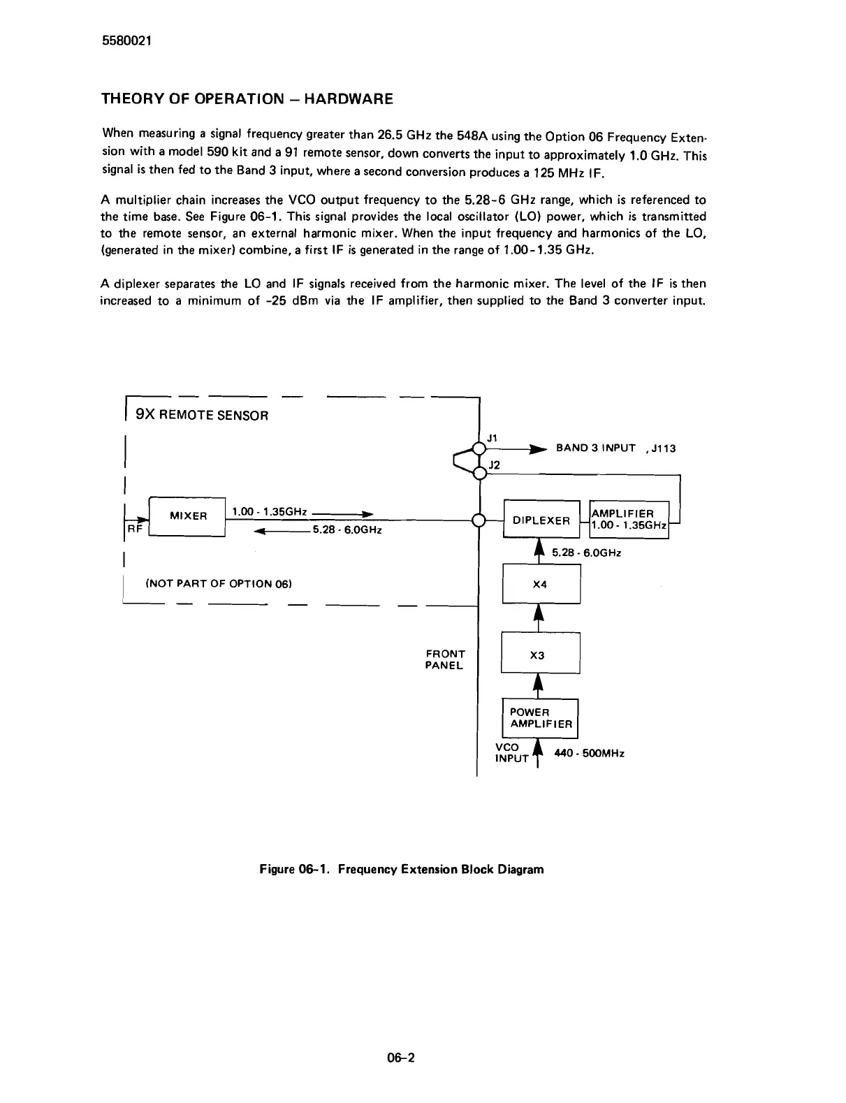
When measuring
a
signal frequency greater than
26.5
GHz
the
548A
using the Option
06
Frequency Exten-
sion with a model
590
kit and a
91
remote sensor, down converts the input to approximately
1.0
GHz.
This
signal
is
then fed to the Band
3
input, where a second conversion produces
a
125
MHz
IF.
A
multiplier chain increases the VCO output frequency to the
5.28-6
GHz
range, which
is
referenced to
the time base. See Figure
06-1.
This signal provides the local oscillator (LO) power, which
is
transmitted
to the remote sensor, an external harmonic mixer. When the input frequency and harmonics of the LO,
(generated in the mixer) combine, a first
IF
is
generated in the range of
1.00-1.35
GHz.
A
diplexer separates the LO and IF signals received from the harmonic mixer. The level of the IF
is
then
increased to a minimum of
-25
dBm via the IF amplifier, then supplied to the Band
3
converter input.
-
--
)E&
SENSOR
(NOT PART OF OPTION 061
1-
-
--
BAND 3 INPUT
,
J113
$+*
,
FRONT
PANEL
Figure
06-1.
Frequency Extension Block Diagram
Scans by ArtekMedia © 2007