All frequency checks and adjustments should be made only after the oscillator has been connected to
its
power source for 24 hours. If the oscillator has been disconnected from
its
power source for more than
24 hours
it
may require 72 hours of continuous operation to achieve the specified frequency aging rate.
To measure oscillator frequency:
1.
Connect the counter's internal oscillator output signal from the 10 MHz
IN/OUT connector (on the
rear panel of the counter) to the vertical input of the oscilloscope.
2.
Trigger oscilloscope externally with the frequency standard. The VLF Comparator
is
used to determine
the absolute frequency of the standard.
3. Set oscilloscope sweep rate to 0.1
C(
seclcm and expand X10; this results in a sweep rate of .O1
C(
sec/cm.
4.
Adjust oscilloscope vertical controls for maximum gain.
5.
Determine the frequency difference (see page 6-24).
6. Horizontal drift of oscilloscope display in
C(
seclsec,
is
a measure of the difference between the fre-
quency standard and the counter oscillator frequency. If the difference
is
excessive for the desired
counter application, vary the
TlME BASE ADJUST control on the rear panel of the counter until
the pattern stops drifting.
NOTE
For highest accuracy, the counter should be operated
for 72
h~urs prior to adjustment.
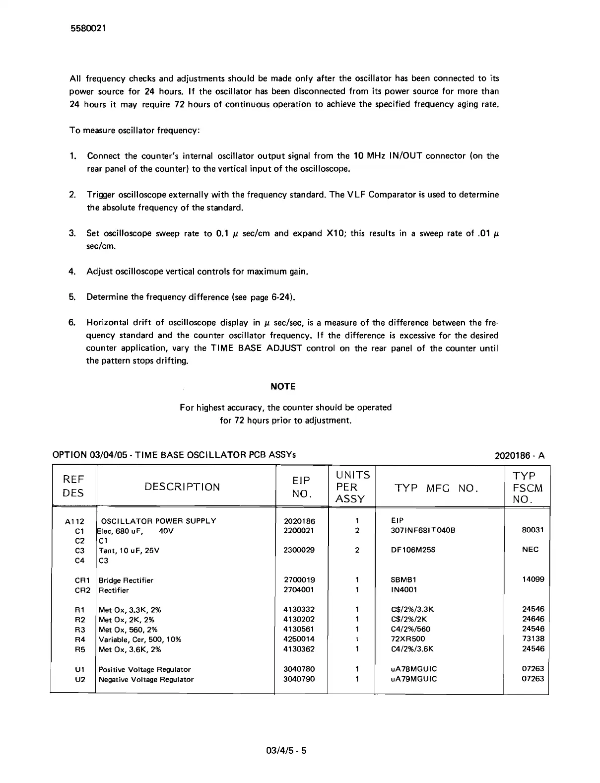
OPTION 03/04/05
-
TIME BASE OSCl LLATOR PCB ASSYS
20201 86
-
A
REF
D ES
A1 12
C1
C2
C3
C4
CRl
CR2
R1
R2
R3
R4
R5
U1
U2
DESCRI PTlON
OSCILLATOR POWER SUPPLY
Elec, 680
uF, 40V
C1
Tant, 10 u F, 25V
C3
Bridge Rectifier
Rectifier
Met Ox,
3.3K. 2%
Met Ox,
2K. 2%
Met Ox, 560.2%
Variable, Cer, 500, 10%
Met Ox,
3.6K. 2%
Positive Voltage Regulator
Negative Voltage Regulator
No.
20201 86
220002 1
2300029
2700019
2704001
41 30332
41 30202
41 30561
425001 4
41 30362
3040780
3040790
UNITS
PER
ASSY
1
2
2
1
1
1
1
1
I
1
1
1
TYP MFG NO.
EIP
3071NF681 T040B
DF106M25S
SBMBl
I
N4001
C$/2%/3.3K
C$12%12K
C4/2%/560
72XR500
C4/2%/3.6K
uA78MGUIC
uA79MGUIC
TY P
FSCM
NO.
80031
NEC
14099
24546
24646
24546
73138
24546
07263
07263
Scans by ArtekMedia © 2007