89
Maintenance
Maintenance details
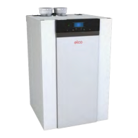
The ignition electrode
The ignition electrode (1) is a
consumablepartandmustbechecked
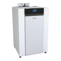
Checking the air pressure
dierential switch + side
- Switchotheboiler
- Disconnect the silicon hose on
the + side (P1) of the air pressure
dierentialswitch(1).
annually.Theelectrodemustbe
renewed, if damages or any wear and
tear is detected. The value of ignition
electroderesistancecanbedetected
through measurements.
The maximum electrode resistance at
room temperature should not exceed
100Ω.
Itcanbereplacedunscrewingitfrom
the heat exchanger. Remove and
replace the o-ring. Make sure of the
tightness of the connection.
In case electrode damage is detected,
verify the status and eventually replace
thefusealongelectrodecable.
In order to ensure continued good
andsafeoperationoftheboiler
ignitionelectrodeshouldbereplaced
every 2 years.
The detection electrode.
The detection electrode (2) is a
consumablepartandmustbechecked
annually.Theelectrodemustbe
renewed, if damages or any wear and
tearisdetected,butcertainlyevery4
years. Furthermore, the value of the
ionizationcurrentcanbedetected
through measurements. Under full load
operations, the minimum ionization
currentmustamountto4μA.
Itcanbereplacedunscrewingitfrom
the heat exchanger. Remove and
replace the o-ring. Make sure of the
tightness of the connection.
Sight glass
If the sight glass (3) is damaged, it can
bereplacedunscrewingitfromthe
heat exchanger. Remove and replace
the gasket. Make sure the gasket is in
correct position and the connection of
new glass is tight.
Assemblyisdoneinreverseorder.
2
1
3
P
1
(
+
) P
2
(-)
(
+
)
1
3
2
4
5
6
- Take a large plastic syringe
orbellowsandconnectaTpiece
with a hose connected (2).
- Connect the + side of the air-
pressuredierentialswitchtoone
end of the T piece with a hose (3).
- On the other end of the T piece,
connect the + side of a pressure
gauge (4).
- Turnontheboiler.
- Pushthesyringeorbellowsinvery
slowlyuntiltheboilergoesinto
failure mode (5).
- Make a note of the pressure
indicatedbythepressuregauge
at that point. A switch pressure of
between5.0and6.5mbarisne.
A lower or higher switch pressure
indicatesaproblemwiththeair
pressuredierentialswitch.
- After taking a measurement, detach
the silicon hose from the T piece on
the + side and reconnect the hose
that was previously removed.
CAUTION:
Please note: The + side (P1) is the rear
connector nipple of the air pressure
dierential switch (without red cap).
- Remove any soiling from all
connection points for hoses and the
airpressuredierentialswitch.
- Check the condition and tightness
of the hoses of the air pressure
dierentialswitch.Replacethe
hoses if necessary.