5-18
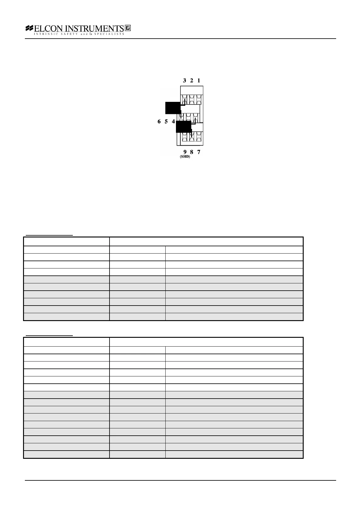
If the Termination Board configuration is know when ordering, the junction compensator is fitted on the board
during configuration phase. If the compensator must be installed lately (on the field), it can be obtained from Elcon
(PN. 205029) and connected to the board using the input terminals as described above and in figure below.
Note: For thermocouple type “B” the reference junction compensator is not necessary and the cable must be
connected as for mV input shown on block diagram.
The unit can be used with all Elcon standard termination board except the /HAKE.
Connection Information
Please refer to the electrical schematics above and to the electrical connection section 4.7.
For more details please refer to the Termination Board Instruction Manual.
Model HiD 2061:
Screw terminal number Used for
11 Safe area output +
14 Safe area output -
19 Safe area Shield
12, 13, 15, 16, 17, 18 not used
1 Hazardous area TC input +, mV input +
7 Hazardous area TC input -
4 Hazardous area CJC compensator for TC +
8 Hazardous area CJC compensator for TC -, mV input -
9 Hazardous area Shield
2, 3, 5, 6 not used
Model HiD 2062:
Screw terminal number Used for
11 Safe area output +, Ch. 1
14 Safe area output -, Ch. 1
12 Safe area output +, Ch. 2
15 Safe area output -, Ch. 2
19 Safe area Shield
13, 16, 17, 18 not used
1 Hazardous area TC input +, mV input +, Ch. 1
7 Hazardous area TC input -, Ch. 1
4 Hazardous area CJC compensator for TC +, Ch. 1
8 Hazardous area CJC compensator for TC -, mV input -, Ch. 1
2 Hazardous area TC input +, mV input +, Ch. 2
5 Hazardous area TC input -, Ch. 2
3 Hazardous area CJC compensator for TC +, Ch. 2
6 Hazardous area CJC compensator for TC -, mV input -, Ch. 2
9 Hazardous area Shield