MODEL 1000 SEP 2005
INSTALLATION AND SETUP
3-23
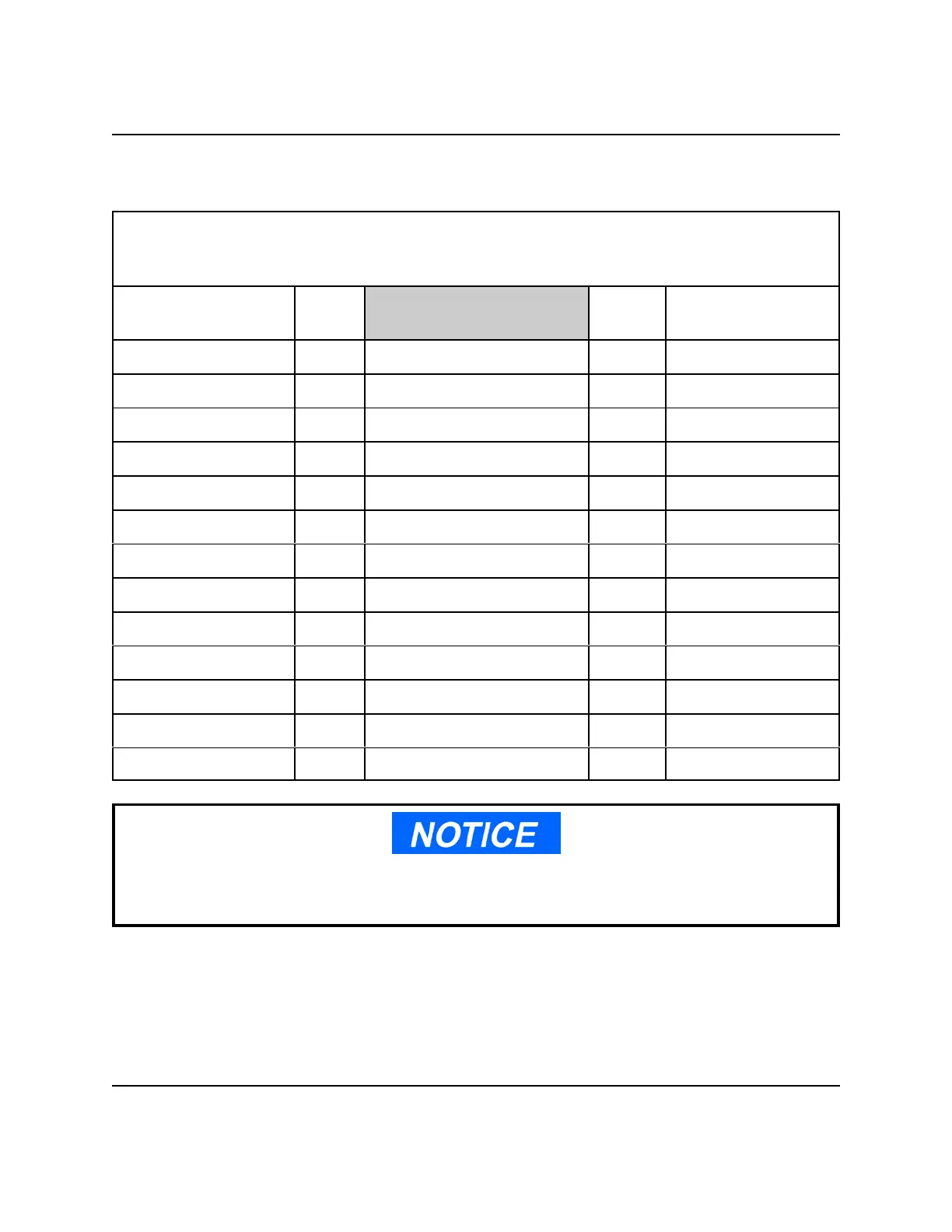
Table 3-2. Point-to-Point Wiring Guide, Analyzer and GC Controller
Board Acronyms:
- Interconnect Terminal Board of Analyzer (TB-4)
- Terminal Board for Field Wiring at Controller (TB)
Analyzer
(TB-4)
color color
Controller
(TB)
Terminal 11 Function code 1 J19, Terminal 1
Terminal 12 Function code 2 J19, Terminal 2
Terminal 13 Function code 4 J19, Terminal 3
Terminal 14 Function code 8 J19, Terminal 4
Terminal 15 Function code strobe J20, Terminal 1
Terminal 16 Common - function codes J19, Terminal 5
Terminal 17 Auto Zero (AZ) J20, Terminal 2
Terminal 18 Preamp gain channel 1 J18, Terminal 1
Terminal 19 Preamp gain channel 2 J18, Terminal 4
Terminal 20 Preamp gain channel 3 J18, Terminal 7
Terminal 21 Preamp gain channel 4 J18, Terminal 10
Terminal 22 Common - preamp gain J18, Terminal 11
Terminal 23 Alarm function (AF) J20, Terminal 3
Connect the interconnect cable SHIELD to one terminal; specifically, terminal 12 of J18, on
the GC Controller TB.
 Loading...