PACSystems VersaMax Genius Network Interface User Manual Section 5
GFK-1535D Jan 2023
Configuration 94
I/O Module Configuration Data Format
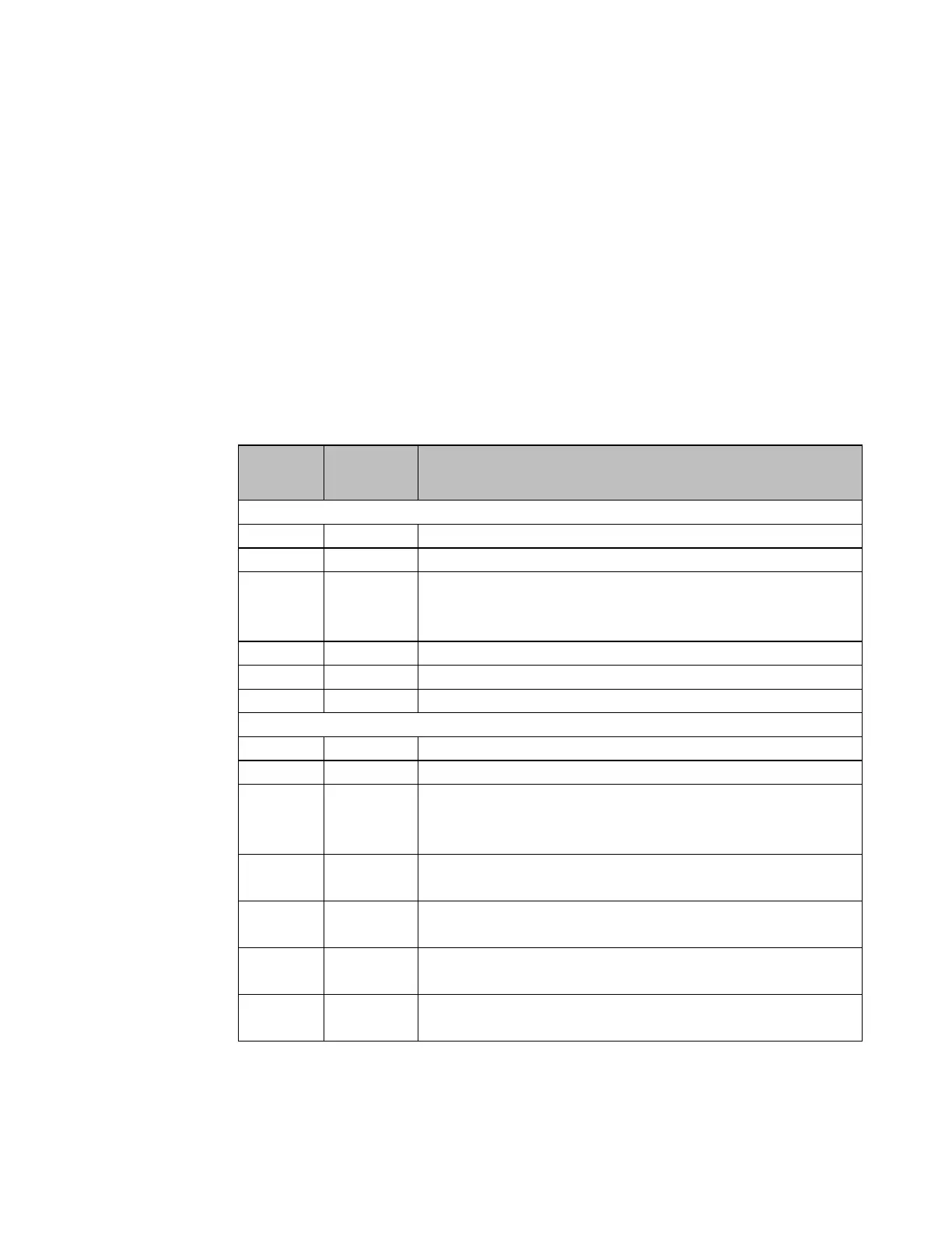
Configuration data for I/O modules follow the same format for all non-
intelligent I/O modules, analog or discrete, input, output, or mixed. The
configuration datagram contains a VersaMax configuration message
header, a rack/slot header, fixed I/O configuration fields, variable-length
configuration fields, and module-specific data. The total length of fixed
and variable I/O configuration fields and module-specific data must be a
multiple of 26 bytes. Pad bytes set to a value of 0 are appended to the
end of the module-specific data to meet this requirement. Fixed and
variable-length configuration fields appear according to the mapping
shown in the table below.
I/O Module Format (Rack 0-7, slot 2-9)
secondary board ID (MSB in 0, LSB in 1)
primary board ID (MSB in 2, LSB in 3)
ASCII string. Set to zeros during auto-configuration, the
programmer may fill this field with an arbitrary identification
string.
Length of additional data (excluding pad bytes)
Length of additional data (excluding pad bytes)
Fixed I/O configuration fields
Secondary board ID (same as above.)
Primary board ID(same as above)
Offset from the start of fixed I/O configuration fields to module-
specific data. The length of module-specific data is given at offset
18 below.
The number of discrete input reference description fields listed in
the input segments list below. (may be 00)
Number of discrete output reference description fields listed in
the output segments list below. (may be 00)
Number of analog input reference description fields listed in the
input segments list below. (may be 00)
Number of analog output reference description fields listed in the
output segments list below. (may be 00)
 Loading...