PACSystems VersaMax Genius Network Interface User Manual Section 2
GFK-1535D Jan 2023
Installation 20
2.3 Mounting Instructions
Each rack in a VersaMax I/O Station must be installed on a single section
of 7.5mm X 35mm DIN rail. “Rack” is the term used for an NIU or
Expansion Receiver, plus up to 8 physically connected I/O carriers. The
first rack in a system is called Rack 0. If there are multiple expansion
racks, Rack 0 also includes an Expansion Transmitter module installed in
the leftmost position, before the NIU.
The DIN rail used in a VersaMax installation must be electrically grounded
to provide EMC protection. The rail must have a conductive (unpainted)
corrosion-resistant finish. DIN rails compliant with DIN EN50032 are
preferred.
For vibration resistance, the DIN rail should be installed on a panel using
screws spaced approximately 5.24cm (6 inches) apart. DIN-rail clamps
(available as part number IC200ACC313) can also be installed at both
ends of the station to lock the modules in position.
For applications requiring maximum resistance to mechanical vibration
and shock, the NIU and DIN-rail-mounted carriers should also be
mounted on the panel, as described on the next page.
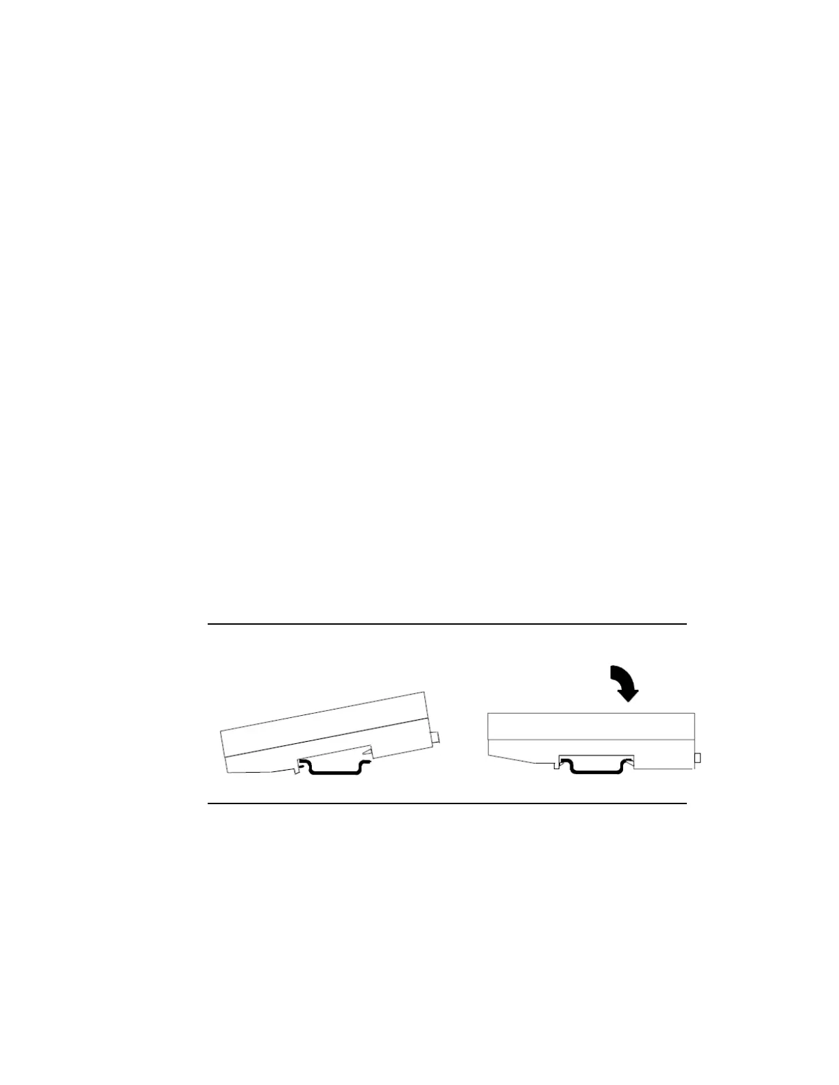
The base snaps easily onto the DIN rail. No tools are required for
mounting or grounding the rail.
Figure 12: Mounting a VersaMax Module
 Loading...