PACSystems VersaMax Genius Network Interface User Manual Section 2
GFK-1535D Jan 2023
Installation 24
2.5.1 Removing an Expansion Transmitter Module
1.
Make sure the rack power is off.
2.
Slide module on DIN rail away from the NIU in the main rack.
3.
Using a small screwdriver, pull down on the tab on the bottom of
the module and lift the module off the DIN rail.
2.6 Installing an Expansion Receiver Module
An Expansion Receiver Module (IC200ERM001 or 002) must be installed in
the leftmost slot of each VersaMax expansion “rack”.
1.
Insert the label inside the access door at the upper left corner of
the module.
2.
Attach the module to the DIN rail at the left end of the expansion
rack.
3.
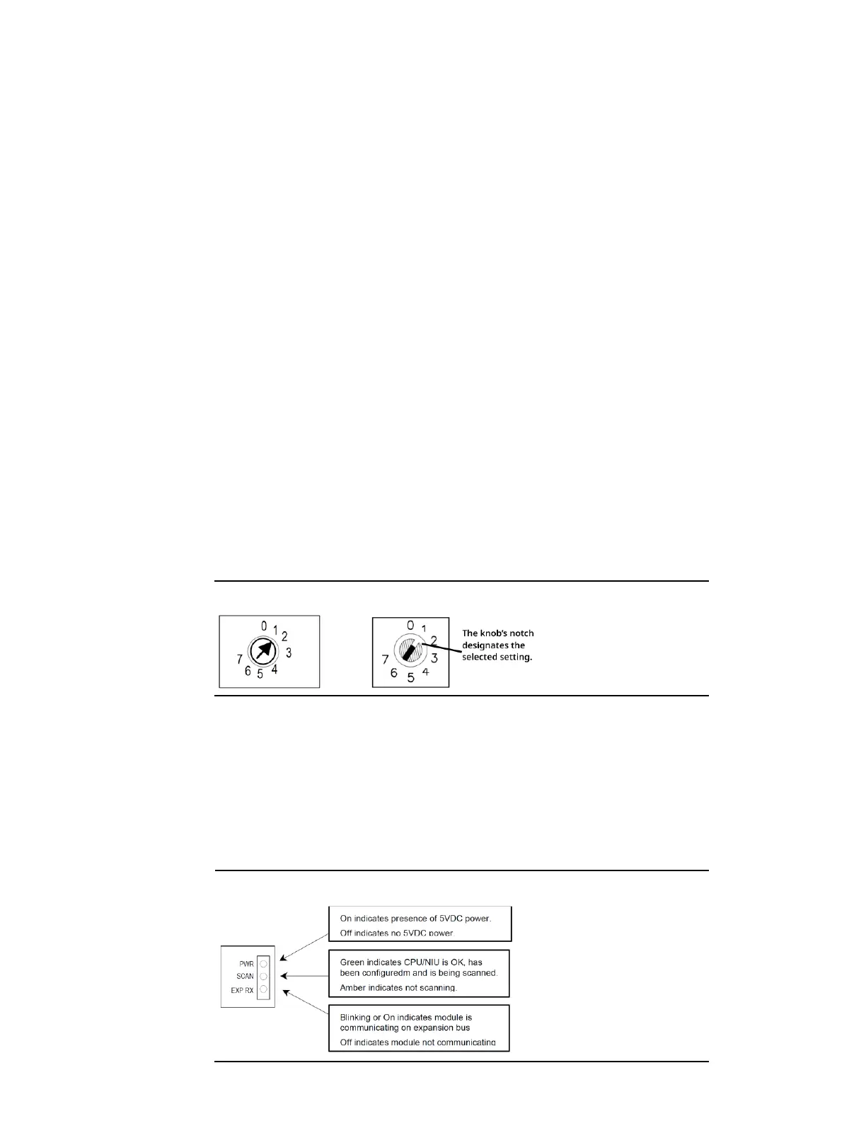
Select the expansion rack ID (1 to 7) using the rotary switch under
the access door at the upper left corner of the module. Duplicate
Rack IDs are not permitted. In a single-ended expansion system,
the receiver Rack ID must be set to 1.
Figure 17: Old Rotary (Left) and New Rotary (Right) Switches
4.
Install the Power Supply module on top of the Expansion
Receiver.
5.
Attach the cables. If the system includes an Expansion
Transmitter Module, attach the terminator plug to the EXP2 port
on the last Expansion Receiver Module.
6.
After completing any additional system installation steps, apply
power and observe the module LEDs.
Figure 18: Power Indicators