PACSystems VersaMax Genius Network Interface User Manual Section 4
GFK-1535D Jan 2023
Configuration 61
4.1 Station Racks and Slots
Even though a VersaMax I/O Station does not have a backplane with a
fixed number of slots, both the programming software and the
autoconfiguration process use the conventional labels of racks and slots
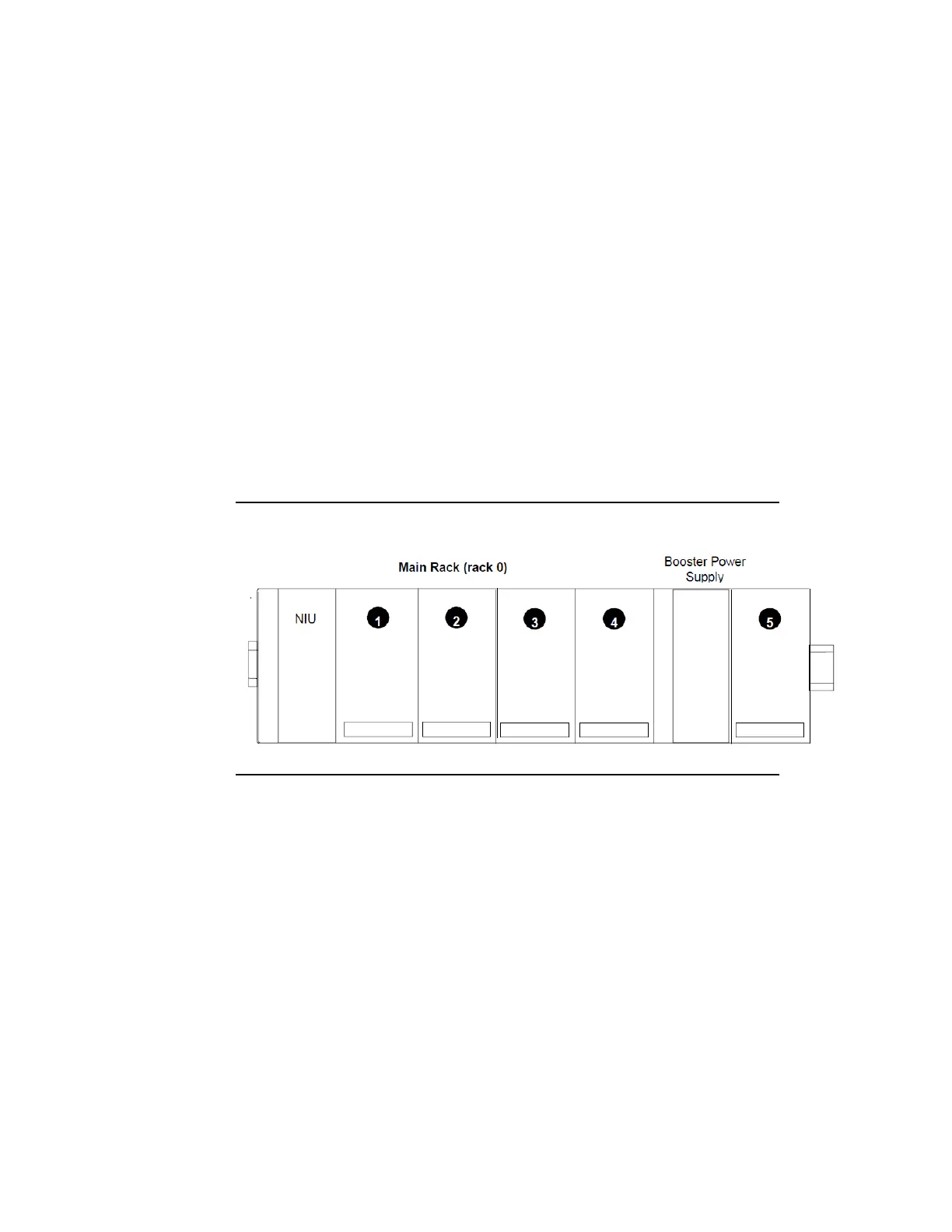
to uniquely identify modules in the station. Each rack consists of an NIU
or an Expansion Receiver module plus up to 8 additional I/O modules
mounted on a common DIN rail. Each I/O module occupies one slot. The
slot immediately to the right of the NIU or Expansion Receiver module is
called slot 1. Booster power supplies do not count as occupying slots.
The rack that contains the NIU is called the main rack and is labeled rack
0. An example main rack is pictured below. Optionally, additional racks
may be attached to the main rack via Expansion Receiver modules. These
racks are called expansion racks and are labeled racks 1 to 7.
Figure 41: Example Station Racks/Slots